ES-1495/
G-1175
FIGURE8-7. ROTOR BEARING REMOVAL
Rotor
Bearing
Replacement
1 . Clean the bearing and shaft mating surfaces.
2.
Apply Loctite #680 adhesive to the shaft mat-
ing surface.
3.
Apply Loctite #747 activator to the bearing
mating surface.
4. Install the bearing and allow ten minutes curing
time before handling the assembly.
Ignition
Components
The ignition rotor and ignition module are located
inside the generator. When the stator in its housing
has been removed, the ignition rotor can be re-
moved/replaced on the crankshaft, and the ignition
module can be removed/replaced on the generator
adapter housing as follows (see Figure 8-8).
8-11
Ignition
Rotor
Removal/Replacement
To remove the ignition rotor, simply pry
it off using a
dull-edged pry bar or other implement. To install
the ignition rotor, place it over the end of the crank-
shaft, line the key on the rotor up with the corre-
sponding slot in the end
of
the crankshaft, and tap
the rotor gently into place.
Ignition
Module
Removal/Replacement
1. Unscrew the red and black wires extending
from the ignition module to the ignition coil.
Make certain to note which wire attaches to
which terminal on the coil.
2.
Unscrew the two screws holding the ignition
module in place on the generator adapter.
3. When the ignition module is loose, pull the red
and black wires through the gap in the genera-
tor adapter.
To replace the module, perform the steps listed
above in reverse order.
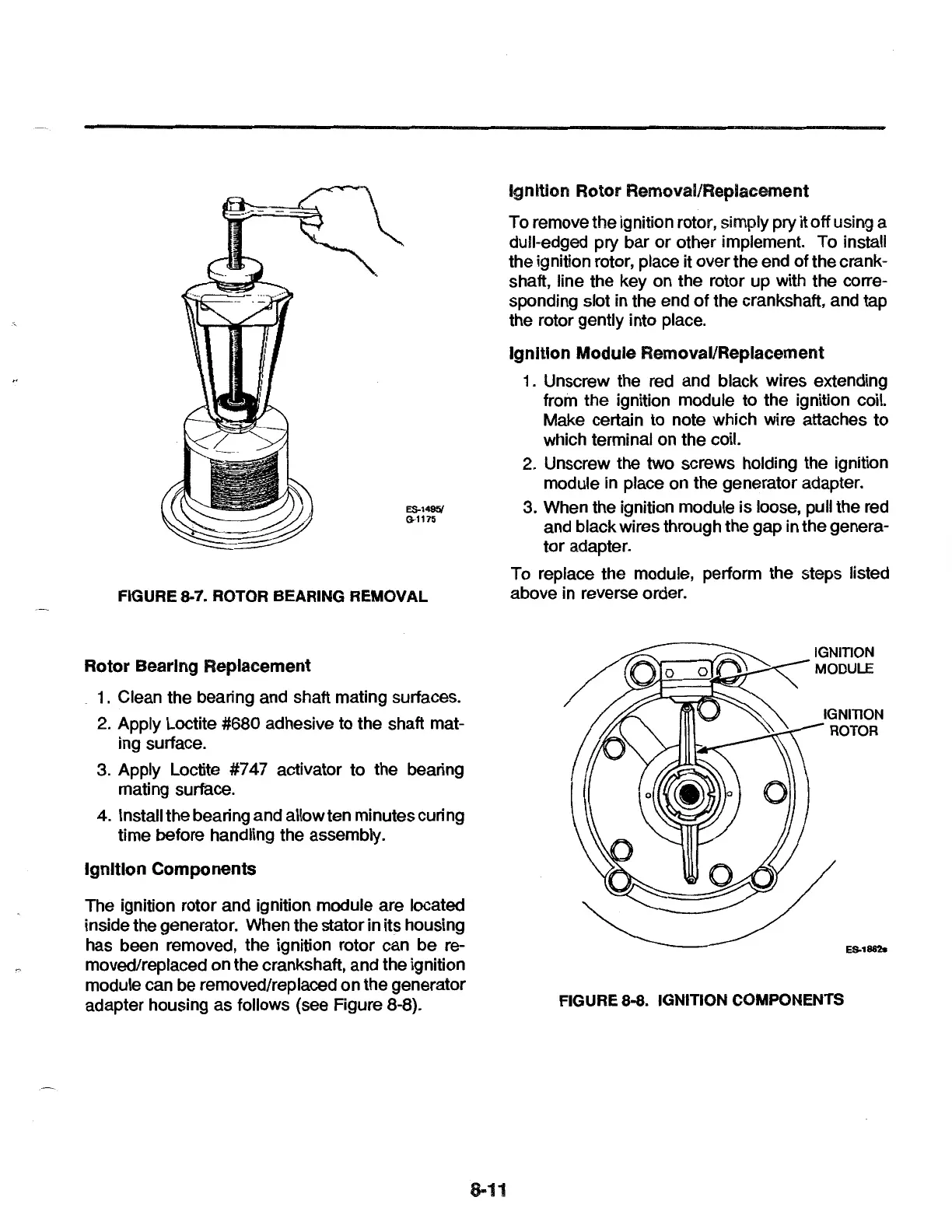
IGNITION
ROTOR
ES.1&H.
FIGURE 8-8. IGNITION COMPONENTS
 Loading...