oneida-air.com 15
Assembly Instructions (Continued)
Mark
Here
16"
406 mm
4"
102 mm
1/2"
13 mm
FIG. 4
FIG. 3a
FIG. 3b
FIG. 5
Wall
Mark
Here
3
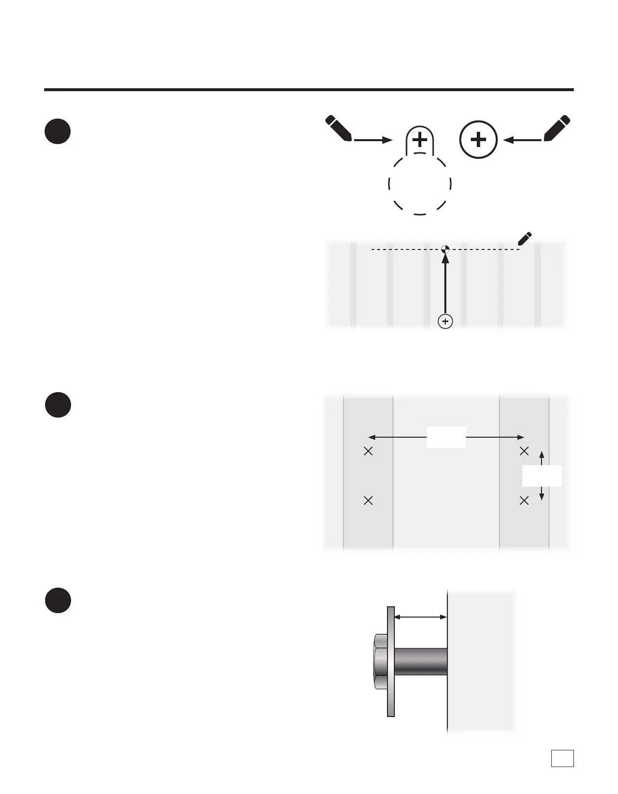
Place a mark through the Template's (G1)
paper at each indicated crosshair (four keyway
holes and one center hole), then remove the
Template (G1) from the wall [FIG. 3a].
Measure 15-1/4" up from the center hole and
mark a straight level line to help with the
install of the Rear Support Brace (G13) [FIG.
3b].
Note: e line you have marked for the Support
Brace is where the fasteners will be installed to.
Refer to Step 9 for more information.
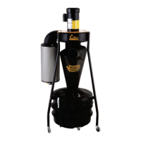
4
Using appropriate fasteners for the wall type
you are installing your system onto, drill into
and install fasteners into the wall at all marked
locations [FIG. 4].
a. Maximum Fastener Size: 5/16" diameter for the 4
keyholes
b. Maximum Fastener Size: #12 screw for the rear
support brace holes
c. Maximum Washer Size: 3/4" outside diameter
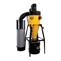
5
Place washers onto each fastener and thread
the fasteners into all four holes, leaving at least
1/2" outside of the hole to t the Wall Bracket
(F) and Rear Support Brace (G13) [FIG. 5].