
B
Brittany McneilAug 15, 2025
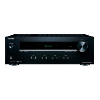
What to do if my Onkyo TX-L5 doesn't switch on?
- JJeffery MartinAug 15, 2025
If your Onkyo Receiver doesn't switch on, there might be a few reasons: * The power cord may be disconnected. Ensure it's properly connected. * The main power might be off. Turn the main power on. * External noise could be interfering with the receiver's circuits. Try switching the main power off and on again. If that doesn't work, disconnect and reconnect the power cord. * The AC fuse might be blown. In this case, contact your nearest Onkyo service center.