Installation
- 24 -
optek-Manual--1004-2001-02--AF16-US-2011-01-04
www.optek.com
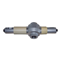
6.3 Airpurge
Should the temperature of the process medium be too low, the temperature of
the air inside the optical housing might fall below dew point. This leads to con-
densation deposits on the window surfaces. For that case, there are airpurge
connections on the window rings of the sensor body or on the optical housings
of the sensor.
Note!
If the product is more than 10 °C (18 °F) cooler than the ambient air of the sen-
sor, always connect airpurge.
Tool • Screw driver
• wrench 7 mm
At delivery, the drill holes of the air purge connections are sealed with O-Ring
and sealing screws M5 x 6 (DIN 84).
1. Remove the sealing screws and O-Rings.
2. Check if there are O-Rings on air purge connections.
3. Install air purge connections (24, fig. 17) screwing.
4. Place the air purge hoses on the air purge connections (24).
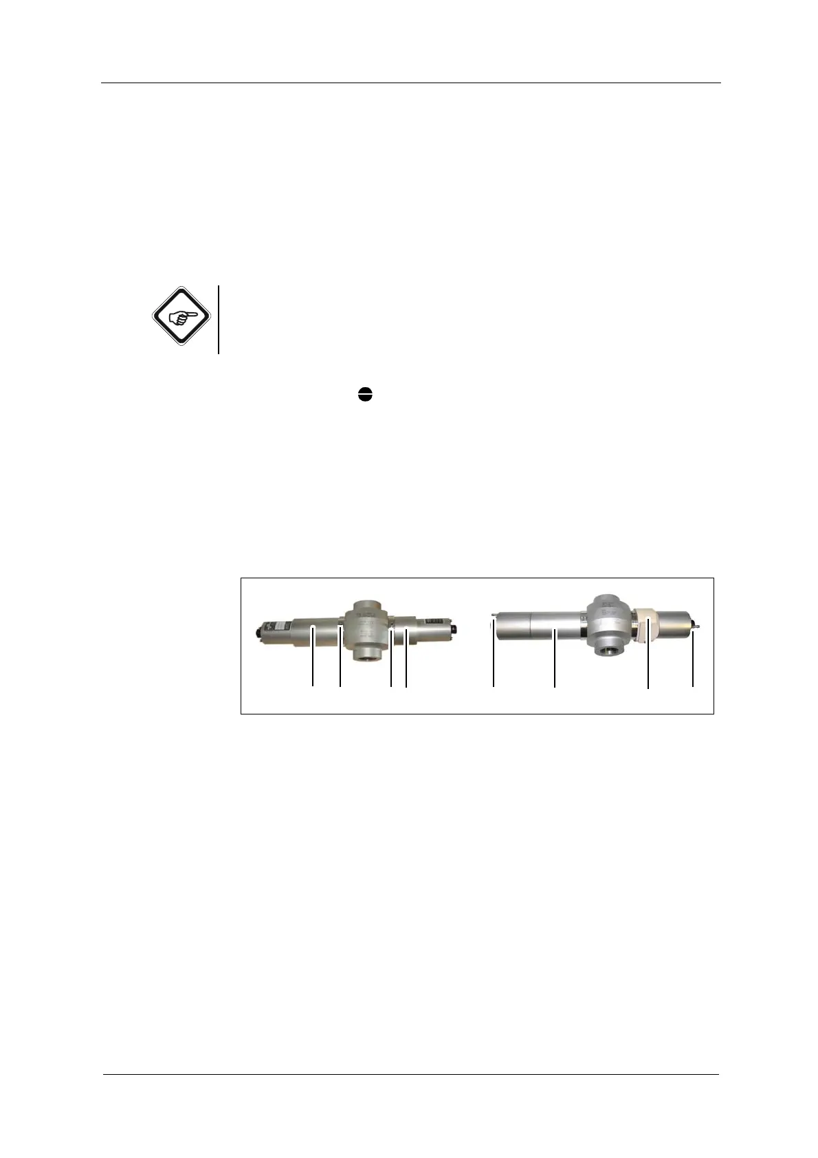
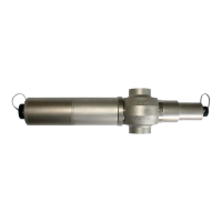
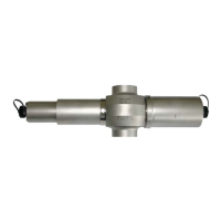
Fig. 17 Window ring air purge connections (left) and optical housing air purge connections (right)
After connecting the sensor to the power supply and putting it into operation,
rinse it as described below:
1. Loosen the two adapters (4,12) turning each 2-3 turns anticlockwise.
2. Rinse the optical housings by aerating them with dry, oil and dust free air for
approx. 10 minutes at a maximum of 0.5 bar (7.25 psi) gauge pressure.
In case you do not have airpurge supply of appropriate quality, you can use
the optek Air Drying System ADS.
3. Reduce air pressure to approx. 0.1 bar (1.45 psi).
4. Retighten the adapter. Keep up the gauge pressure. Air consumption in this
operational state is minimal.
5. Make sure the O-Rings are fitted correctly.