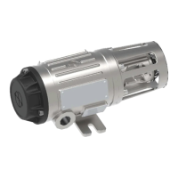
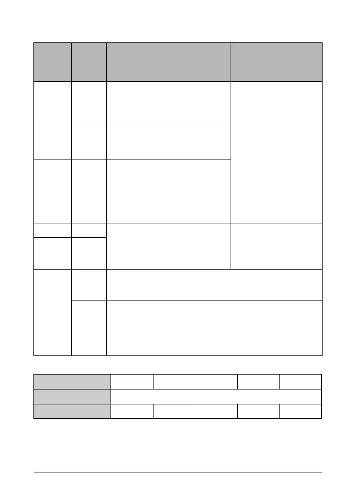
Table 1. Specifications of terminals.
Terminal
(detector
wire
color)
Power,
Positive
supply
voltage
According to site
requirements and Table 2.
Min. cross section:
0.14mm²
Max. cross section:
2.5mm² (Stranded)
4mm² (Solid)
Power,
Supply
voltage
return
Analog 0 - 20 mA DC signal overlayed
with a HART signal. Signals levels
described in table 4. The HART signal is
not interfering with the analog DC
signal and is described in a separate
chapter.
Maximum impedance 500 Ω.
Two wires for connection to digital
RS-485 serial communication, Modbus
RTU.
Industrial communication
cable with shielded twisted
pair. Min/max cross section
0.14/2.5 mm² (stranded) or
max 4 mm² (Solid)
External grounding shall be used when the detector is installed in an
Ex zone.
Normally not used. Shield of the cable is typically connected to
instrument earth in the central control cabinet, and is normally not
terminated at the detector.
If extra RFI protection is required, and the installation's grounding
principles/regulations allow it, the shield can be terminated to local
ground via the internal earth point at the detector.
Table 2. Minimum voltage to PG11 shall be 18 VDC. Examples of cable and maximum length.
* For a nominal power of 24 V. Longer cable can be used with higher supply voltage.
Document 022-80036-OM Revision R03 Page 17 of 48