DRAFT
Proprietary and Confidential
COMPONENT OVERVIEW
Acme Packet 1100 Hardware Installation Guide 13
USB port is for Acme Packet use only and is not to be used by the customer unless
directed by a customer service representative.
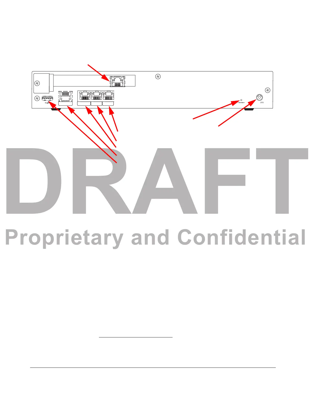
Rear Panel Network management and other ports are located on the rear of the chassis.
SER MGT NET MGT
LNK ACT
INT
LNK ACT
EXT
LNK ACT LNK ACT
12V
USB Port
INT Ethernet Port
NET MGT Ethernet Port
SER MGT Ethernet Port
EXT Ethernet Port
Reset Button
T1/E1 Connector
12V DC Power Connector
T1/E1
Figure 2 - 4. Acme Packet 1100 Rear Panel
Table 2 - 1.
Power Connector 12V of DC power is supplied to the 12V DC power connector via an external AC
power supply. (Options are available for providing a country-specific AC cable.)
Reset Button A hard reset of the Acme Packet 1100 can be performed by pressing the reset button.
This bu
tton is recessed and can only be pressed by inserting a thin wire (e.g., a paper
clip) through the reset button channel. Pressing the reset button can result in the loss
of software data or your configuration.
Pressing the reset button causes a hard reset
by immediately rebooting the Acme
Packet 1100. After the reset button is released, the Acme Packet 1100 begins its boot
sequence and loads the configured software file.
T1/E1 Connector
(
O
ptional)
The optional T1/E1 port allows for connection to a TDM connection. The T1/E1 port
is an RJ45 port available on a PCIe card that mounts in the spare slot on the rear of
the chassis. The T1/E1 connector provides a backup line in case the ISP fails. The
prevalence of legacy PSTN in many enterprises makes this a viable option for use as
a backup communications line.
1
EXT Ethernet Port The EXT 10/100 Mbps Ethernet port allows for connection to a SIP trunk from a
service
provider. The INT and EXT Ethernet ports are media ports.
2
1.) In the ACLI the T1/E1 port is referred to as s2p0.
2.) In the ACLI software, the EXT port is referred to as s0p1.
 Loading...