21
1 General
1.1 Symbols and abbreviations in these instructions
• Bullet point, listing
1. Numbered steps with stipulated sequence
2.2
Cross-reference to Section (e.g. 2.2) or separate instructions (but then without figures)
14 Figure cross-reference (e.g. to Fig. 13)
SP Abbreviation for "Short Press" (<0.5 sec.)
LP Abbreviation for "Long Press" (>0.5 sec)
VLP "Very Long Press" (>10 sec)
DP "Double Press" (each <0.5 sec)
i
Symbol "INFORMATION"
1.2 Intended use
This product has been developed and is intended specifically for use with light management sys-
tems for luminaires. Any other use other than that described in these instructions is not intended.
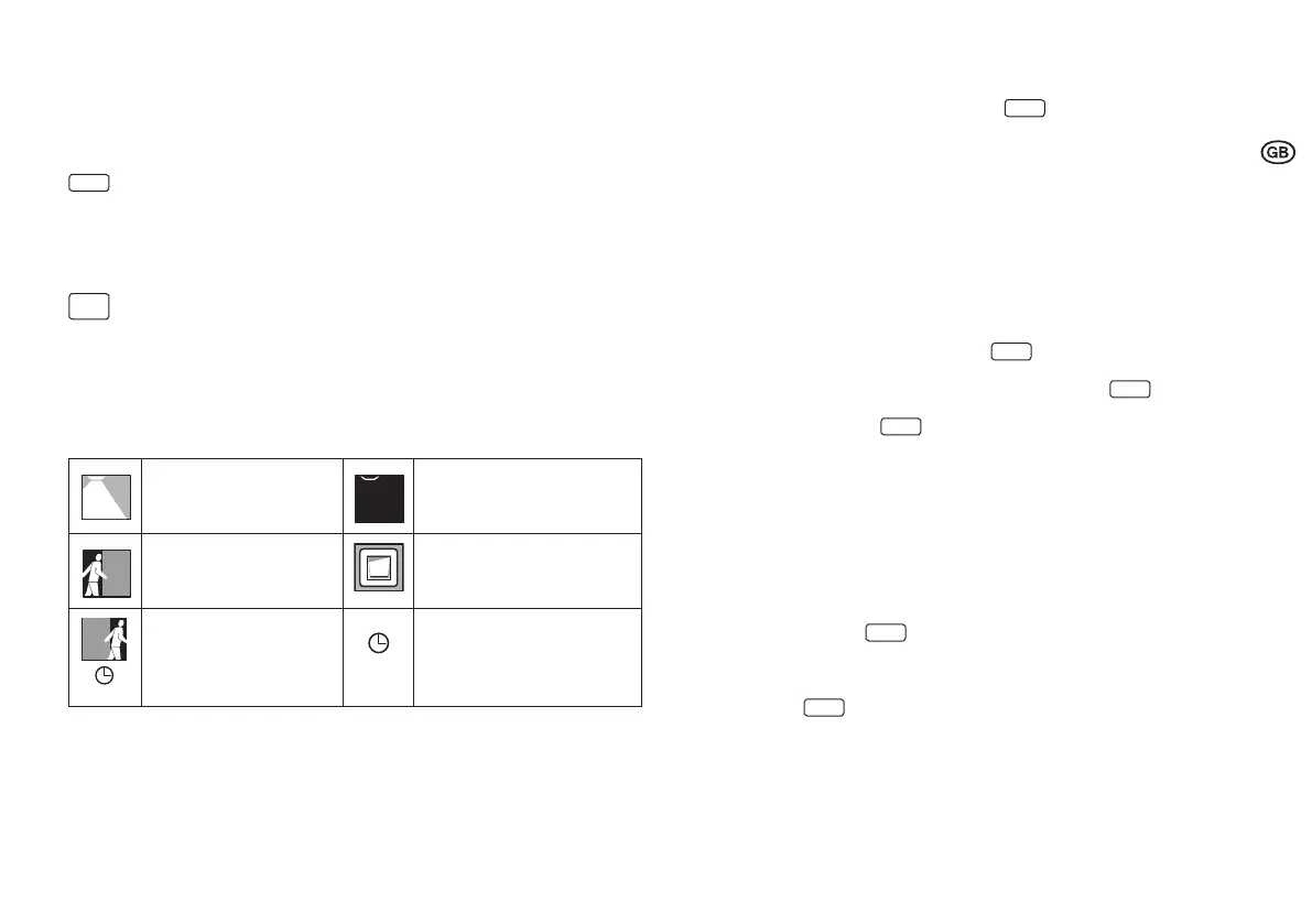
Symbols used in the diagrams
Luminaire is switched on:
"ON"
Luminaire is switched off:
"OFF"
Automatic switching on of the
lighting by motion detection.
Manual switching on of the lighting
by external switch.
Delay period 1:
After leaving the motion
detection area.
Delay period 2
2 Mounting and installation
2.1 Connection allocation in the control unit
3
(1) Mains connection
(2) Mains connection
(3) Spare
(4) DALI 1(-)
(5) DALI 1(+)
(6) DALI 2(-)
(7) DALI 2(+)
(8) Sensor connection (4p4c)
(9) Input external push-button
(10) Sync connection (no function)
(11) GND - Reference potential external push-button
2.2 Dimensions and mounting dimensions 2
2.3 Connection diagram for electrical system components
4
2.4 Sensor and networking
5
The sensor is provided for luminaire integration. Installation and settings on sensor separate
instructions.
Connection of max. 4 sensors (3) via Y-connector (4) and sensor cable (2) to sensor connection
on control unit (1).
Requirements for sensor and luminaire position:
• Entire workplace (to be monitored) is within monitoring area of the sensor.
• Avoid direct radiation of the sensor by light sources (incorrect measurements).
• The sensor must not be installed in areas where there is a draft (air conditioning/ventilation)
or heat sources (photocopier/hot air blower) (incorrect sensing of persons moving).
2.5 External push-button 4
Push-button for manual control/setting. Connection conditions 8.
2.6 Connection of additional sensors and push-buttons via
the DALI line
6
Additional push-buttons and sensors can be integrated using coupling units that can be
connected directly to the two DALI lines. The function does not depend on whether connection is
via DALI channel 1 or 2. Up to three couplers can be connected to each DALI channel, in addition
to the 16 DALI ECGs.
min.
min.