䊳
Pulse-Accu RT-NRT
This measured value is same as Accu RT-NRT. However, the threshold is deter-
mined by the resolution of the pulse output (0.05 mm · 0.1 mm · 0.2 mm · 0.5
mm · 1.0 mm).
T
he measured value is output as a pulse sequence using a rate of 5 Hz (default)
or 2 Hz (con figurable through the OTT Pluvio
2
S operating software via USB
interface).
Output delay: refer to Accu RT-NRT
Pulse factor (selectable): 0.05 mm · 0.1 mm · 0.2 mm · 0.5 mm · 1.0 mm
(1 mm =
^
20 · 10 · 5 · 2 · 1 Impulse(s))
Resolution: 0.05 mm · 0.1 mm · 0.2 mm · 0.5 mm · 1.0 mm
Recommended sampling interval: continuous pulse counting
Recommended storing interval: any time between 1 minute and 24 hours
䊳
Pulse status information
This measured value corresponds to the current bucket level and additionally
shows status information. Moreover, status information may be used as an
alive signal.
0 pulses/min system error, device or cable at the pulse output faulty
(output #2)
10 … 100 pulses/min 0 … 100 % of the approx. bucket level
120 pulses/min maintenance by means of operation through USB
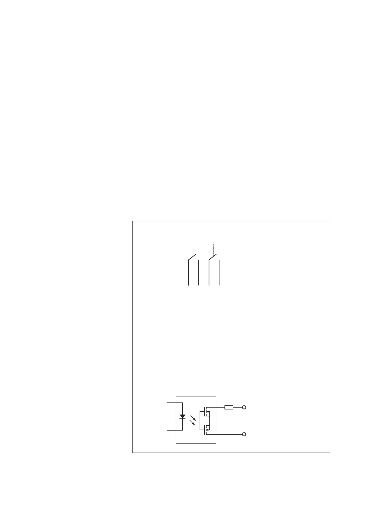
Fig. 2: Pulse output circuit diagram.
The locations of the terminals
are shown in Fig. 13.
Output #1: Terminals #1 and #2.
Output #2: Terminals #3 and #4.
Pulse OUT mm/inch A
Pulse OUT mm/inch
B
Pulse OUT Status A
Pulse OUT Status B
1 2 34
I
max
: 100 mA*
U
m
ax
: 28 V
D
C
Terminals 2 + 4
Terminals 1 + 3
10 Ohm
Simplified schematic diagram
Detailed diagram
Terminals
internal optoelectronic relay
* short circuit protected; load cut-off at 200 mA
10