5.7 Connecting the connection cable
䡵 Push rubber grommet with connection cable into the slot.
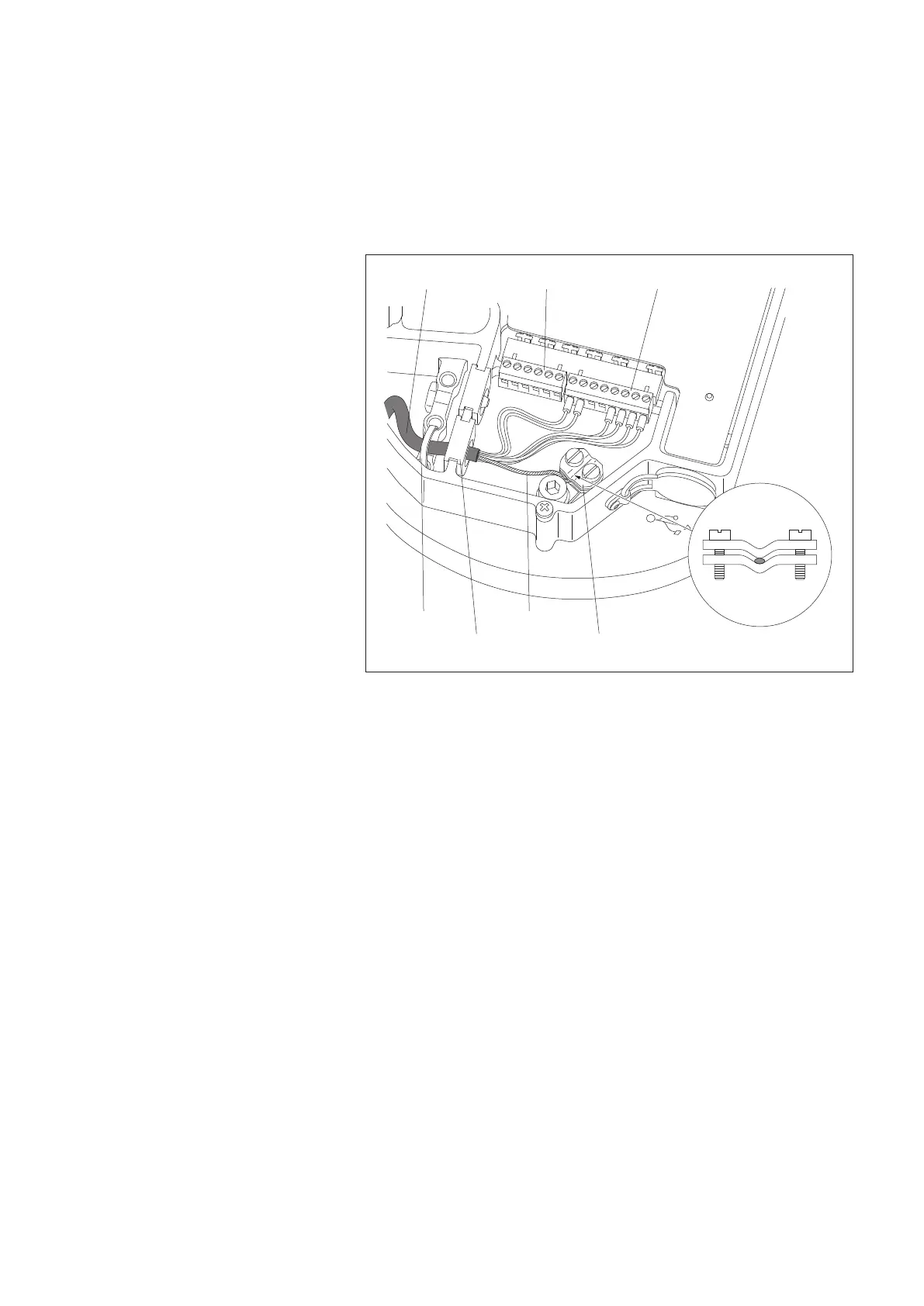
䡵 Connect 6-wire and 8-wire screw terminal strip to the appropriate PCB sockets.
䡵 Connect the twisted shielding of the cables to the terminal, refer to Fig. 13.
䡵
If necessary, pull back connection cable and store in pedestal (raise base plate
again if necessary).
䡵 Push a cable tie through the holes in the base plate and fix the connection
cable using the cable tie.
5.8 Connecting the grounding cable
䡵 Cut the grounding cable (cross-section 10 mm
2
) to approx. 25 ... 30 cm.
䡵 Strip off approx. 10 mm of the grounding cable insulation and connect to the
earth terminal on the base plate underside. For a stranded grounding cable:
push on ferrules and crimp using crimping pliers.
䡵 If necessary, pull back the grounding cable and store in pedestal (lift the base
plate once more if necessary).
䡵 Connect the other end of the grounding cable to a foundation or earthing rod.
Connecting cable
Shield terminal
ShieldCable tie
Rubber grommet
8-wire screw terminal6-wire
Fig. 13: Connecting the cable
in the electronics unit.
(The Figure shows the example of a
standard RS-485 wiring (2-wire) with
optional orifice rim heater. The orifice
rim heater is supplied separately.)
23