+12 … +24 V
DC
Pulse Out mm/inch A
Pulse Out mm/inch B
Pulse Out Status A
Pulse Out Status B
Data RS-485 TX - B
Data RS-485 TX - A
GND
Heating GND
Data GND
Heating +24 V
D
C
SDI-12 Data
Data RS-485 RX - A / R S - 4 8 5 - A
Data RS-485 RX - B / R S - 4 8 5 - B
SDI-12 default
wiring
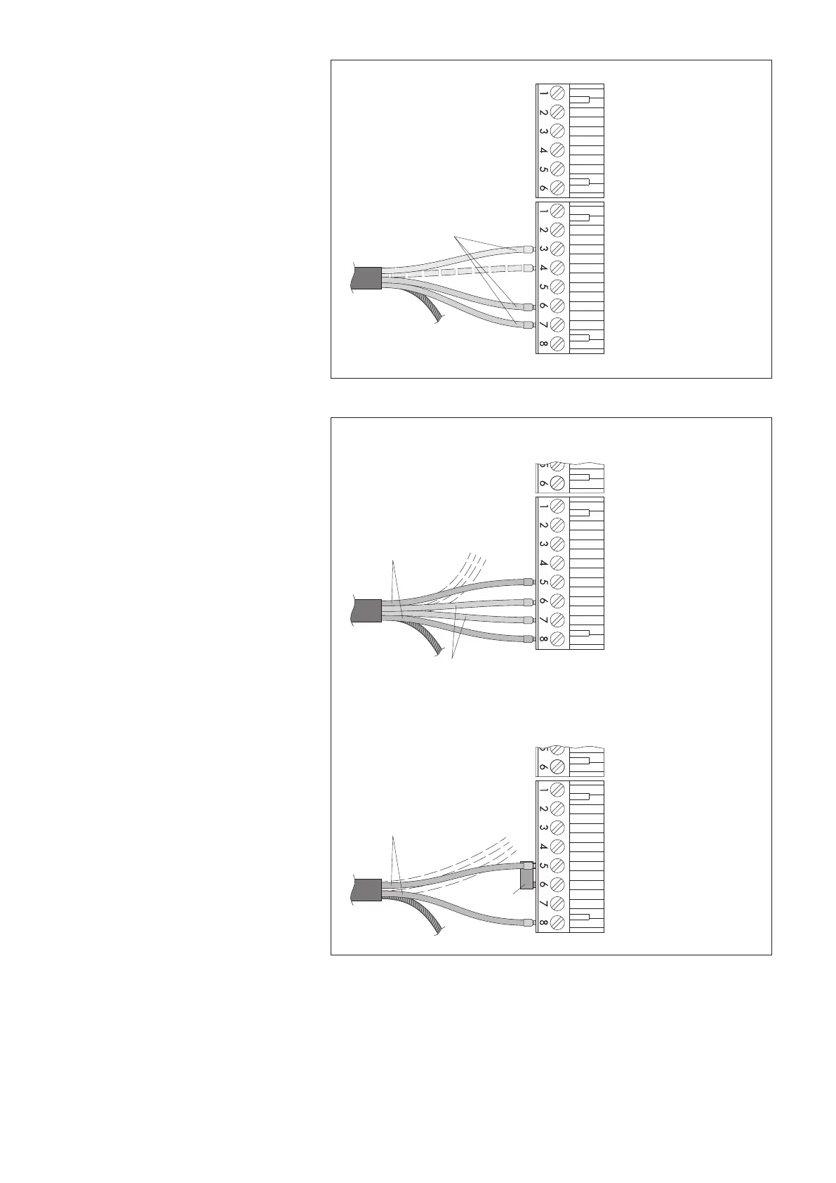
Fig. 10: Connecting the cable for the
data recording device/power supply for
the precipitation gauge to 6-wire and/or
8-wire screw terminal strip (example
SDI-12 interface).
Standard SDI-12 wiring has three wires
(SDI-12 DATA, GND, and power supply
(+12 V)). For separate power supplies, an
additional GND wire is available.
Contacts 4, 6, and 8 of the 8-wire screw
terminal strip are jumpered internally!
Power supply for
heater; 24 V
DC
precipitation gauge; 12 … 24 V
D
C
Jumper
Method B: common power supply for heater and precipitation gauge
Method A: separate supply for heater and precipitation gauge
+12 … +24 V
DC
GND
Heater GND
Data GND
Heating +24 V
D
C
SDI-12 Data
Data RS-485 RX - A / R S - 4 8 5 - A
Data RS-485 RX - B / R S - 4 8 5 - B
+12 … +24 V
DC
GND
Heater GND
Data GND
Heating +24 V
DC
SDI-12 Data
Data RS-485 RX - A / R S - 4 8 5 - A
Data RS-485 RX - B / R S - 4 8 5 - B
Data RS-485 TX - A
Data RS-485 TX - A
Fig. 11: OTT Pluvio
2
S with orifice
rim heater: Connecting options for
power supply of the precipitation gauge
and orifice rim heater.
Please note: For version B, common
supply voltage must be 24 V
DC
!
(Otherwise, heating power is reduced;
refer to "Specifications".)
As necessary, two separate cables may
be used (e.g. separate cable for optional
orifice rim heater).
For clarity, the wires for connecting the data
recording unit are shown as dashed lines.
The jumper is included (polybag
containing installation accessories).
Contacts 4, 7, and 8 of the 8-wire screw
terminal strip are jumpered internally.
21


 To Next Page