62
7.13 Headrest
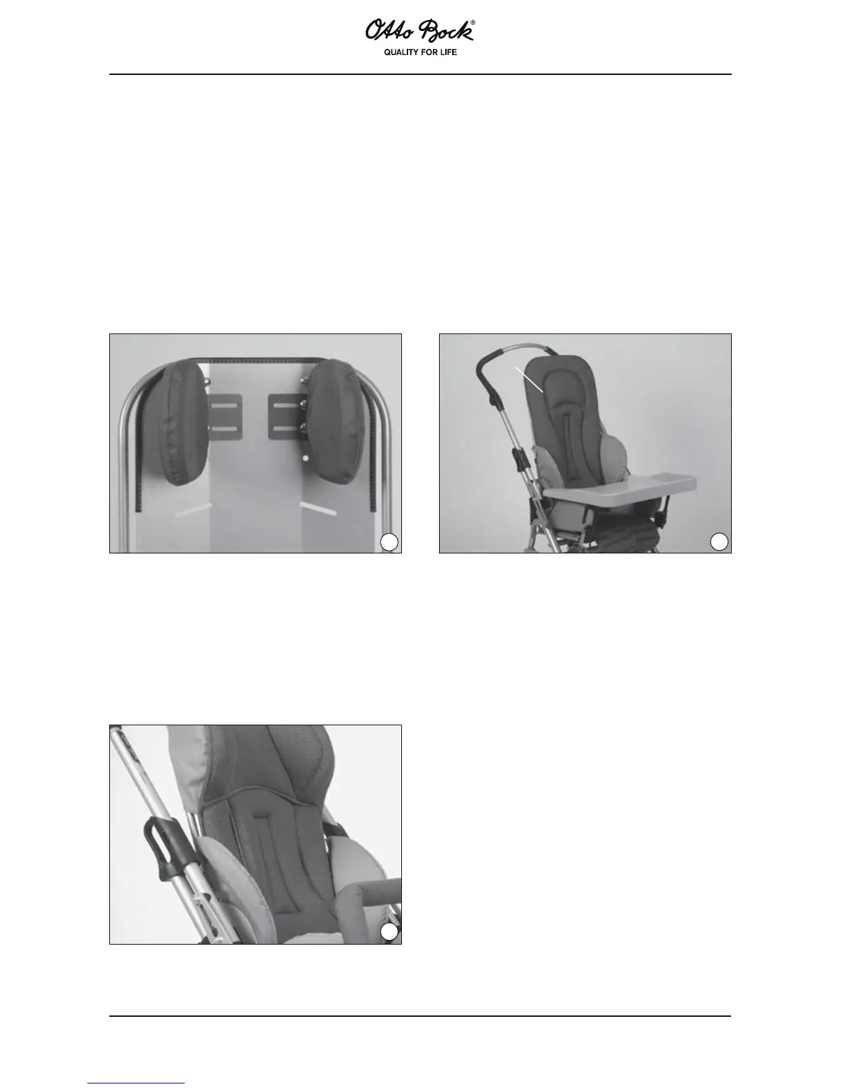
a) Headrest supports
Attach the pair of head supports (Fig. 41) to the back insert with carriage bolts and knurled
nuts. The padding already features four hollow rivets (Fig. 42, item A) for this purpose. To make
installation and adjustments easier, first open the zipper at the top of the back padding.
The head support screws replace the short carriage screws that connect the back frame tube
to the back plate.
Once the knurled nuts have been loosened, the supports can be moved in their slotted holes to
increase or decrease the amount of head room. To vary the height of the headrest, adjust the
back insert (see “Multi-functional Seating Unit“).
41
42
A
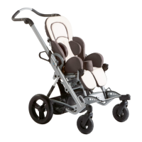
b) Back with Integrated Headrest
The multi-functional seating unit can also be equipped with a back insert with integrated head-
rest (Fig. 43). The procedure for height adjustment is identical to that of the headrest version
described above. The free space for the head can be varied in increments of 1 cm (0.39in) [up
to 3 cm (1.18 in) on each side] by sliding the supplied hard foam pads under the side padding
sections.
43