Torque bolts appropriately for the mount material and bolts. A torque of 146cNm is recom-
mendedfora2stainlesssteelscrews.
UseTIM(ThermalInterfaceMaterial)foranyirregularorun-machinedsurfaces.
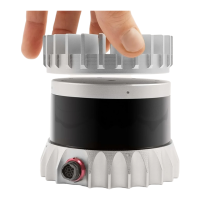
Donotover-constrainthesensorifmountingtoboththetopandthebottom.
Note: Donot mountthedevicesolelyfromthe top. Theprimarymountingattachment siteisatthe
bottomofthedeviceasitensuresadequatemechanicalsupportandruggedness.
Useathermallyconductivepadtoensuregoodconductivitywhilenotoverconstraining.
Ensureyourimplementation maintains the baseand top of the sensorat no greater than 25ºC
aboveambientwithanambientlessthan50ºC.
Theshapeofanyheatsinkshouldmaximizethesurfaceareaforfreeandforcedconvectionwhile
beingthickenoughtoallowtheheattoconductthroughthematerial.
Mountingonadrywall:
When mounting a sensor (needs to be mounted on a baseplate) on a drywall or a false ceiling,
Ousterrecommendsthemountingmeansmustbeabletosupport3Xtheweightofthesensor.
Checkthewallconditionand makesureitsnotaging. Ifyourdrywallisageing or deteriorating,
it’slikelytobowandbendwiththeaddedweightofthesensor,baseplateandcablesconnected
to it. This could cause a potentially dangerous situation where the wall anchors could pull out
andleavethesensorhangingordropdown.
CAD Files and mechanical drawings are provided by Ouster to verify proper sensor and base
platedimensionsthatcanhelpmeasuringthesurfaceforproperplacementandmounting.
Check for studs using a stud finder. As these studs are hidden behind drywall, you’ll need to
locatethem (ifavailable) withastudfinder. Laythe studfinderflaton thewallwhereyouwant
to position your sensor and turn it on. Slowly move it across the wall from left to right until it
beepsorlightsup. Notethelocationwithapencilmarkandcontinuealongthewalluntilyoufind
thenextstud. Continuethisprocessuntilyou’vefoundallthestudswhereyouplantoinstallthe
sensor.
Drillpilotholesandmountthesensorcarefully. Makesureyoucheckforproperinstallationand
thatallscrewsaretightlyfit.
14
 Loading...