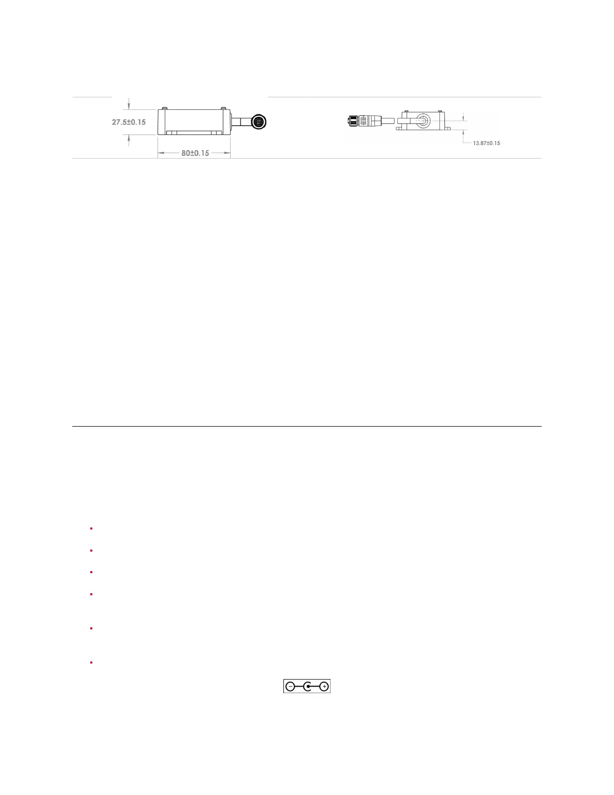
Table7.8: MechanicalDrawing-InterfaceBox(PCBAPN-830-104249)(cntd.)
ForadditionalRev7OS0sensorCADfilesrefertoLidarProductDetailspage.
ElectricalCharacteristics
HighCurrentInterfaceBoxesarerated12VDC,3.3Aand24VDC,1.1A.Theysupport24Voperationon
allOustersensors,and12VoperationforRev5andabovesensorsonly.
LegacyInterfaceBoxesarerated24VDC,1.1AandsupportsallOustersensors.
Over-currentProtection
HighCurrentInterfaceBoxescontainauserreplaceable5Alow-profileminibladefuse. Whenreplac-
ingthisfuse,useonlyaLittelfuse#0891005fuse. Useofanyotherfusemayleadtoariskoffire.
LegacyInterfaceBoxesareprovidedwiththermistortypeover-current protectiontosupplementthe
internal over-current protection in the sensor. The thermistor is soldered in place and is not user
replaceable.
7.4 PowerSupply
TheInterfaceBoxshipswitha24VDC1.5A powersupplyandacordsetsuitableforuse in the U.S.A
and Canada. High Current Interface Boxes are able to operate from a 12VDC source, but a 12VDC
powersupplyisnotprovidedbyOuster.
LegacyInterfaceBoxesareonlydesignedforusewiththesupplied24Vpowersupply.
Toselectapowersupply,itshould:
havea12VDCoutputvoltagerating.
becapableofdeliveringatleast3.3A.
beidentifiedormarkedashavingaLimitedPowerSource(LPS)output.
besafetycertifiedbyanacceptabletesthouseinthelocalregionofuseusingeitherIEC60950-1
orIEC62368-1(ortheENorothernationalequivalent).
beprovidedwithapowersupplycordsetappropriateforthepowersupply’sinputandthesocket
outletsavailableinthelabspace.
beprovidedwithastandard5.5x2.5mmcenter-positivebarrelconnector.
32