DownloadableCADfilesfortheRev7OS0canbefoundonlineatOusterDownloadPage
Warning: ThewateringressprotectionratingforthesensorisonlyvalidiftheI/Ocableisplugged
into the panel mount connector on the base of the sensor, and the locking collet rotated to the
properly locked condition. The cable and plug are an element of the sensor ingress protection
system. Withouttheconnectedcabletheingressprotectionratingmaybecompromised. Bending
the cable at a sharp angle directly after egress from the plug over mold should also be avoided.
Sharpbendsandhighaxialstressesonthecableimmediatelyadjacenttotheplugovermoldmay
createa moistureingresspathintotheconnector. PleaserefertoCable Characteristics formore
informationonminimumbendradiusrequirements.
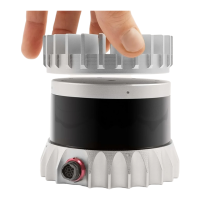
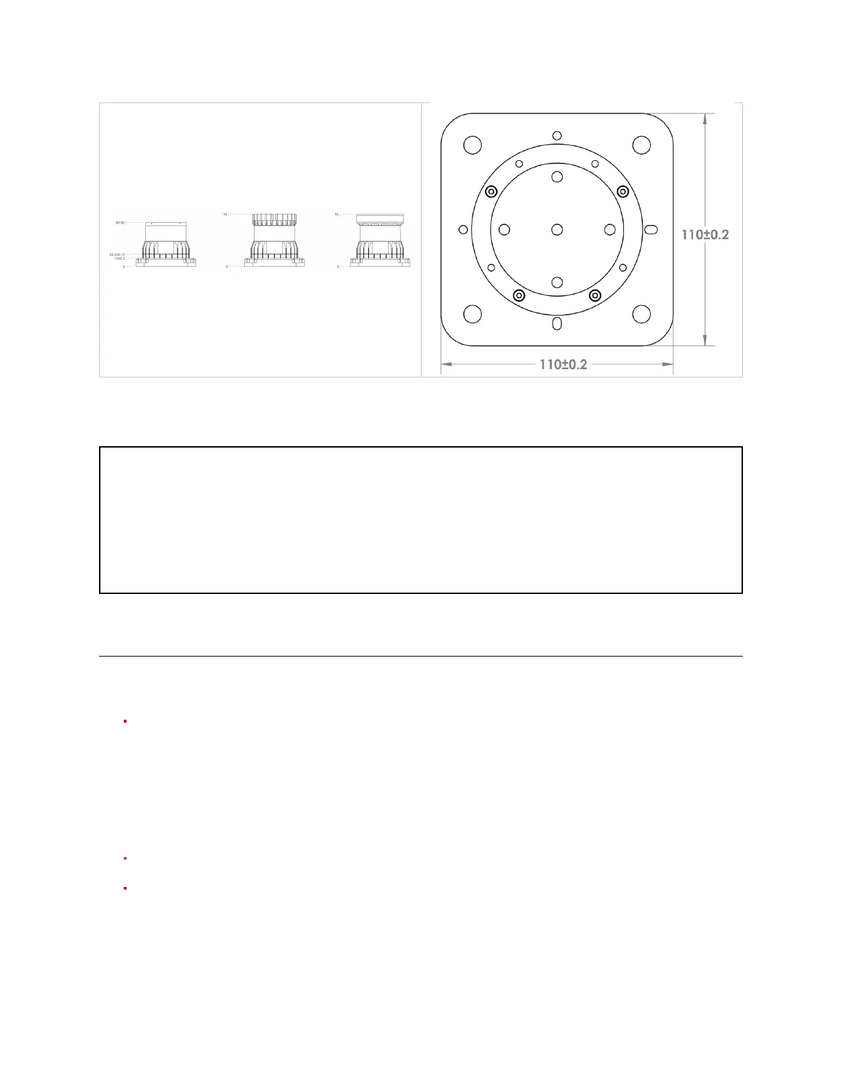
3.3 MountingGuidelines
Our sensors ship with modular mounting options. The sensor can be mounted in any orientation.
Propermountingwillensureoptimalsensorperformanceandefficientheatdissipation.
Mounttoamaterialwith high thermal conductivity. The followingarerecommended aluminum
alloysandtheirthermalconductivities:
1) 6061: 167W/m-K
2) 7075: 130W/m-K
3) 2024: 121W/m-K
Ensureinterfacesarecleanandfreefromdebris.
M3screwsareformountingthesensordirectlytothesurface. M8screwsareusedformounting
thebase platetothesurface. ThescrewholepatternispresentedintheSensordrawingabove
Sensor Components (MechanicalDrawings).
13