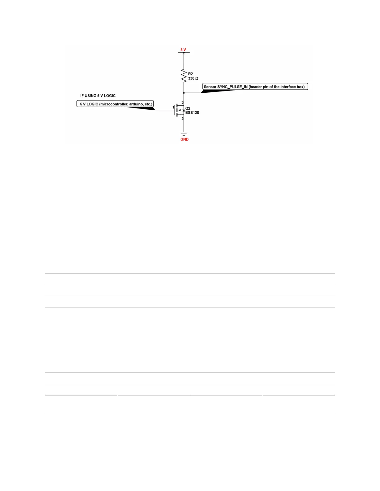
Figure 5.2: ExampleCircuitfor5Vlogic
5.2 MULTIPURPOSE_IO(MIO)
MULTIPURPOSE_IO (MIO)isaconfigurableinputoroutputchannelaccessiblefromtheInterfaceBox. De-
tailedinformationonhowtoconfigurethischannelusingthesensorTCPinterfacecanbefoundinthe
APIguide. Bydefaultthischannelisdisabled.
WhenthischannelisconfiguredasanOUTPUT,theMIO sendsapulsesequencethatcanbeusedfor
timesynchronizationoreventtriggeringoutsidethesensor. Forafulldescriptionofoutputpulsetrig-
geringoptions,refertotheFirmwareUserManualformoreinformation. Thisoutputisanopto-isolated
opencollectorcircuit,relyingonanexternallyprovidedpull-upresistor. Thisresistorisprovidedfora
typical3.3V/5VapplicationaspartoftheInterfaceBoxcircuitry.
Table5.2: MULTIPURPOSE_IO-OUTPUTInterfaceRequirements
Parameter Min Max
PullUpVoltage 3.3V 24V
SinkingCurrent N/A 25mA
When this channel is configured as an INPUT, the MIO can accept a standard NMEA $GPRMC UART
message. These messages are a common way for GPS systems to share timestamp information in
UTCtimeformat. Moreinformationon thispacketstructure andsupportedbaudratescan be found
intheTimeSynchronizationsectionoftheFirmwareUserManual.
Table5.3: MULTIPURPOSE_IO-INPUTInterfaceRequirements
Parameter MinVoltage MaxVoltage MinDriverCurrent
LOGICLOW -30V 2V N/A
LOGICHIGH 2.9V 30V 3mA @3.3V~5V, 5mA
at24Vandhigher
Abovearetestedwith a 35m (200uH inductance)Interface Box at 115200 Baud.
20
 Loading...