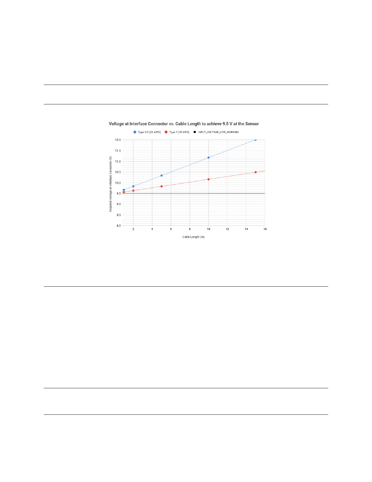
The following graph Voltage at connector vs cable length can be used as a guide to determine the
appropriate input voltage to the sensor connector for your desired cable length. The values on the
graphwerecalculatedusing idealizedcableresistancesderivedfromtheAWGsystemandassumed
maximumpowerdrawfromthesensor.
Note: ForType4,pleaserefertoType3(18AWG)inthegraphbelowastheyhavethesameelectrical
characteristics.
Figure 7.1: Voltageatconnectorvscablelength
7.2 InterfaceBox
AllInterfaceBoxesareprovidedwithaDCpowerportandanRJ45jackforEthernet. CurrentlyOuster
offerstwotypesofInterfaceboxestosupportboth12Vand24V.
Legacy24VnominalInterfaceBoxesprovidedwith Type1andType2cablesareassembledwithin-
tegralcablesforconnectiontoOuster’ssensors.
12V/24VnominalInterfaceBoxeswithType3cablesareprovidedinmodularandintegralcablevari-
ants. The modular variant has a built-in connector and a detachable double-connectorized Type 3
cable for connection to Ouster’s sensors. Whereas, the integral cable variant which is our current
“STANDARD” arenotdetachableandhaveonlyonesidedconnector. BothvariantshaveaGPScon-
nector capable of accepting TTL level signals originating from a separate GPS device that contains
ESDprotectioncircuitry.
Note: Both Legacy and Modular interface boxes are no longer available for purchase, it has been
mentionedinthisusermanualforreference/informationonlyforexistingusers. PleasecontactOuster
salesrepresentativeforquestionsregardingavailableoptions.
23