5 DigitalIO
5.1 SYNC_PULSE_IN
SYNC_PULSE_IN is a dedicated input channel that is accessible from the Interface Box. This channel
expectsaninputpulse sequence which can beusedfortime synchronization. Refertothe Firmware
User Manual for more informationon configuring this input. Any references to pulse polarity in this
documentreferencesthesignalpolarityon the
SYNC_PULSE_IN pinofthe sensor. Thisinputchannel is
protectedbyanopto-isolatorwhichwilldraw5mAatfulloperation.
Table5.1: SYNC_PULSE_INInterfaceRequirements
Parameter MinVoltage MaxVoltage MinDriverCurrent
LOGICLOW -30V 2V N/A
LOGICHIGH 2.9V 30V 3mA @3.3V~5V, 5mA
at24Vandhigher
SYNC_PULSE_IN Interface requirements were tested with 2 m cable Interface Box connection at 2
MHz.
When GPIO has 5 mA drive strength minimum, GPIO can be directly connected to the
SYNC_PULSE_IN pinoftheInterfaceBoxheader. Thisisthemostcommoncaseandhasbeentested
to work on common Arduino microcontroller series. Typical common logic levels of 3.3 V, 5 V
GPIOofmicrocontrollerscanproducedrivestrengthof5mAmin(Arduino,MSP430,etc.).
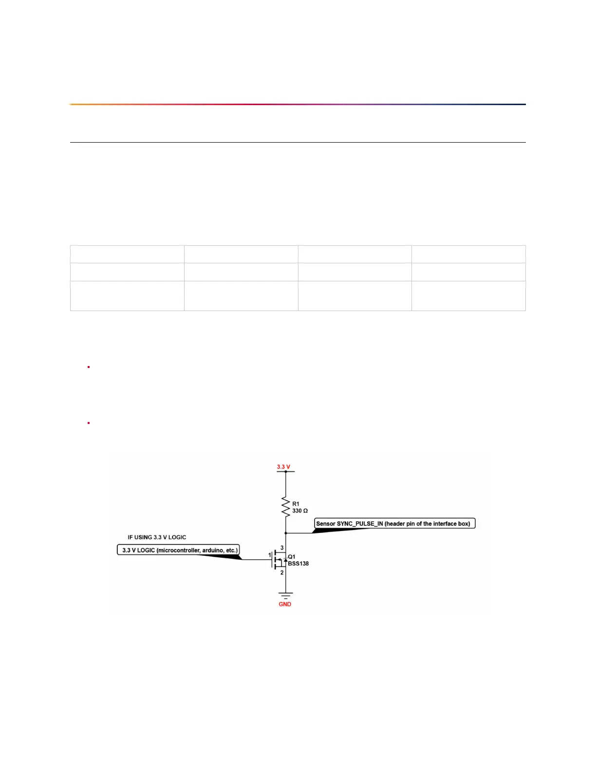
If the 5 mA drive strength minimum cannot be met, a buffer circuit is required to drive
SYNC_PULSE_IN.Examplecircuitsareprovidedforcommon3.3Vand5Vlogic.
Figure 5.1: ExampleCircuitfor3.3V
19