Thecorresponding3D pointcanbe computedby
r = range_mm
n = lidar_origin_to_beam_origin_mm
θ
encoder
= 2π ·
(
1 −
encoder_count
90112
)
θ
azimuth
= −2π
beam_azimuth_angles[i]
360
ϕ = 2π
beam_altitude_angles[i]
360
x = (r − n) cos(θ
encoder
+ θ
azimuth
) cos(ϕ) + n cos(θ
encoder
)
y = (r − n) sin(θ
encoder
+ θ
azimuth
) cos(ϕ) + n sin(θ
encoder
)
z = (r − n) sin(ϕ)
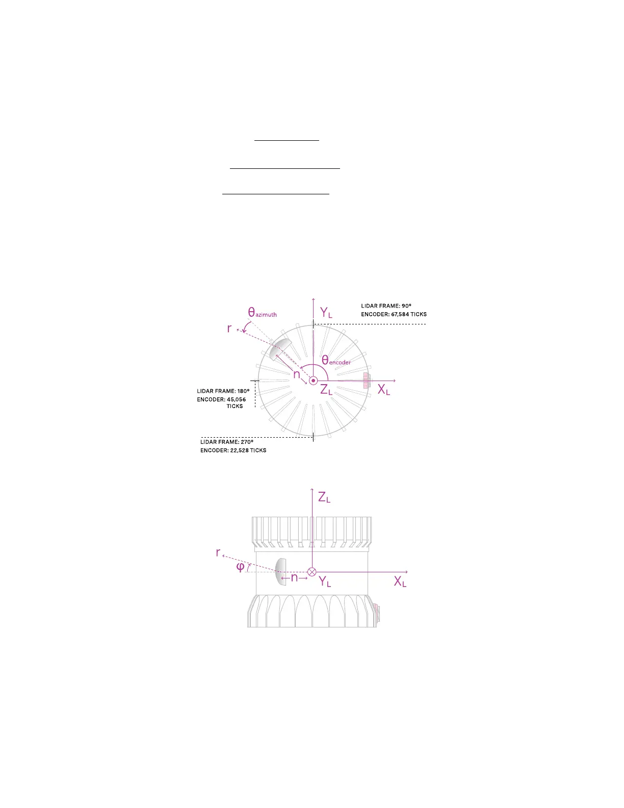
FiguresFig.8.1 andFig.8.2 show,respectively,a top-downand sideview of thesensor.
Figure8.1: Top-down viewof Lidar CoordinateFrame
Figure8.2: Sideview ofLidar CoordinateFrame
12
 Loading...