14 DigitalIO
14.1 SYNC_PULSE_IN
SYNC_PULSE_IN isadedicatedinputchannelthatisaccessiblewithintheInterfaceBoxJumperJ4. This
channelexpectsaninputpulsesequencewhichcanbeusedfortimesynchronization. SeetheSetting
Configuration Parameters for more information on configuring this input. Any references to pulse
polarity in this document references the signal polarity on the SYNC_PULSE_IN pin of the sensor. This
inputchannel isprotectedbyan optoisolatorwhich willdraw10mAat fullturnon.
Table14.1: SYNC_PULSE_INInterface Requirements
Parameter MinVoltage MaxVoltage MinDriverCurrent
LOGICLOW 0V 1V N/A
LOGICHIGH 3.3 V 15V 5mA
SYNC_PULSE_IN Interface Requirements were tested with 2 m cable Interface Box connection at 2
MHz.
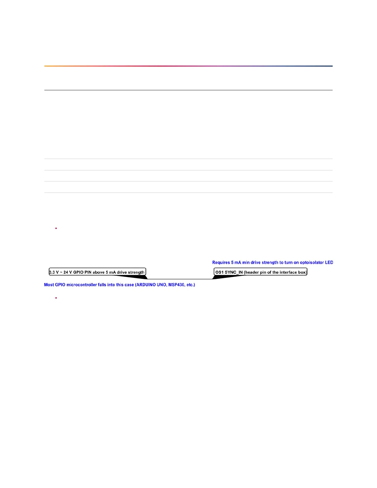
When GPIO has 5 mA drive strength minimum, GPIO can be directly connected to the
SYNC_PULSE_IN pinoftheinterfaceboxheader. Thisisthemostcommoncaseandhasbeentested
to work on common Arduino microcontroller series. Typical common logic levels of 3.3 V, 5 V
GPIOof microcontrollerscan producedrive strengthof 5mA min(Arduino,MSP430,etc.).
If the 5 mA drive strength minimum cannot be met, a buffer circuit is required to drive
SYNC_PULSE_IN.Example circuitsareprovidedforcommon3.3Vand 5Vlogic.
26
 Loading...