CAUTION
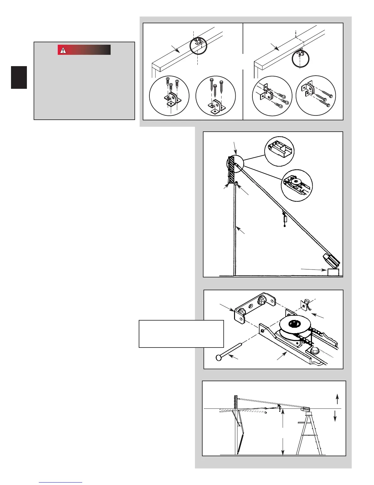
6. Install door bracket (Fig. 2-12).
• Contact door manufacturer for proper installation.
NOTE: Self-drilling screws are intended for use with light-
w
eight door only, while lag screws are meant for wood
doors only.
Because door designs vary, modifications may be
required and additional materials needed. Please contact
your door manufacturer with any questions concerning
your door.
Doors made of masonite,
ligh
tweight wood, fiberglass, and
metal must be properly braced
before mounting
an operator.
Contact door manufacturer
or distributor for
bracing instructions.
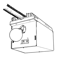
7. Attach channel/rail assembly to header
bracket (Fig. 2-13).
• Fasten header end of the channel/rail to the
header bracket with pin.
• Install speed nut onto pin (Fig, 2-14).
• Place cardboard packing under p
ower head. Use
additional support if needed.
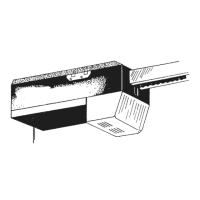
8.
Establish power head mounting height(Fig. 2-15).
• Power head should be at door height above floor
or higher.
• Temp
orarily support power head in this position.
Use
– rop
e.
– ladder with cardboard packing.
– wood.
5. Install door braces
(S
ee CAUTION below).
Header bracket
Header
Door
Power head
(Protec
ted by cardboard
or packing)
Door
bracket
Fig. 2-15
CORRECT
r
WRONG
Door height
Fig. 2-12
Fig. 2-14
Door
bracket
Pin
Speed
nut
Boom header end
Same arrangement applies
to channel (not shown)
Channel
Rail
16
Fig. 2-13
Critical height is point where the rail/channel attaches to power head.
Top of Door
Dessus de la porte
“V”
“V”
“V”
“V”
Top of Door
OR
Top of Door
Dessus de la porte
[
79
]
[
96
]
[
79
]
[
96
]
[
82
]
[
81
]
 Loading...