CAUTION
Mounting bracket must be fastened to garage fram-
ing. Do Not fasten to drywall, particle board, plaster
or other such materials.
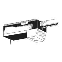
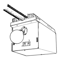
9. Mount power head (See Section 2 ALTERNATE
MOUNTING METHODS).
• Be sure rail assembly and power head are on
do
or center line (line “V”).
• Check the illustrations. Decide which mounting
metho
d you will use. Materials for mounting are
not included.
• After power head is installed, remove
supp
orting material.
• Close door.
10. Join door arms exactly as shown (Fig. 2-16).
• Overlap arms by two (2) holes.
• Install two (2) 3/8” x 7/8” hex bolts, and hex
flange nuts
.
• Tighten hex nuts securely.
11. Install assembled do
or arms (Fig. 2-17).
• Attach straight end of assembled door arms to
door bracket.
– slip straight do
or arm into slot in door bracket.
– secure with clevis pin [90] and cotter pin [89].
• Release carriage (See emer
gency release tag).
• Slide c
arriage toward door.
• Attach short end of curved door arm to carriage.
– slip curved door arm in
to slot in carriage.
– secure with clevis pin and cotter pin.
NOTE:
When opening, door must not pass level posi-
tion or if you are not able to close the door after complet-
ing previous step; a longer door arm is required. An exten-
sion kit can be purchased by calling the Customer
Service phone number, 1.800.354.3643.
12. Adjust emergency release cord length.
• Mount the emergency release knob 6 feet from
the floor.
• Retie overhand knot and trim excess cord.
Fig. 2-17
Fig. 2-16
Straight door arm
Curved door arm
17
OPEN YELLOW PARTS BAG
[
92
]
[
91
]
Bolt, 3/8”-16 x 7/8”
Nut, 3/8-16
[
92
]
[
91
]
3/8-16 nut
Bolt, 3/8-16 x 7/8”
Clevis pin
[
90
]
Cotter pin
[
89
]
[
90
]
Clevis pin
[
89
]
Clevis pin
 Loading...