36
Repair
5. Reposition the unit with the
rear of the power source
facing forward.
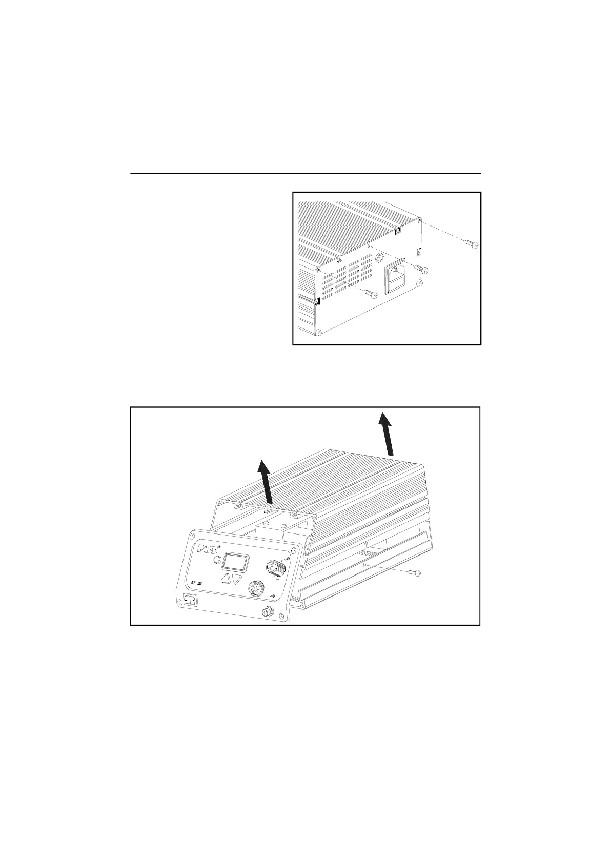
6. Remove the 3 upper Rear
Panel mounting screws.
9. The power source components are now exposed for servicing. When
replacing the Main PCB Assembly or the Motor Pump Asembly, separate
instructions are supplied with the part.
10. To assemble the power source, perform steps 1 through 8 in reverse order,
installing parts (e.g., screws) instead of removing.
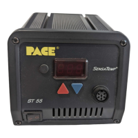
7. A Cover Mounting Screw is located on each side of the power source
(positioned bottom center). Remove the 2 Cover Mounting Screws.
8. Lift the Cover from the power source. Set Cover aside.