User Manual Chapter 3
GFK-2749A Jan 2020
Configuration and Data Transfer 48
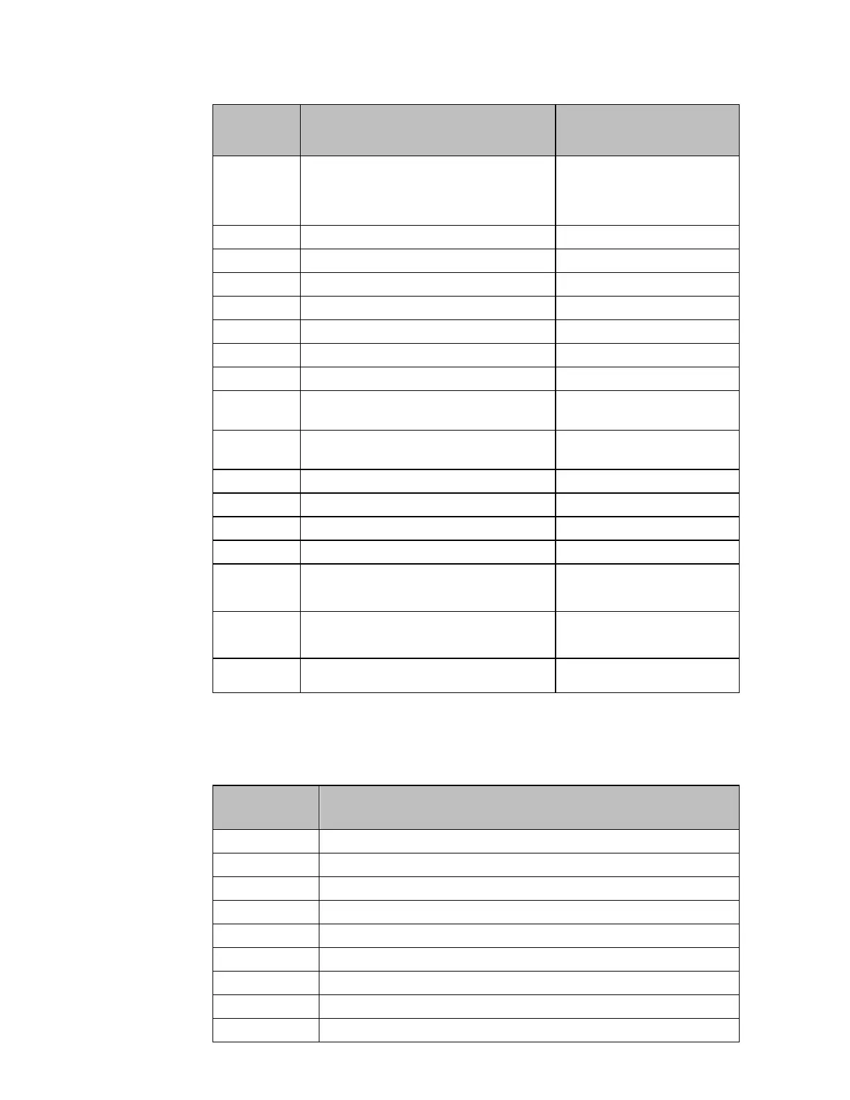
GRID 2– Phase C Current – RMS value
WYE and Delta B-common
configurations Delta C-common
always 0
GRID 2– Phase C Active Power
GRID 2– Phase C Reactive Power
GRID 2– Neutral Current – RMS value
GRID 2– Total Active Power
GRID 2– Total Reactive Power
GRID 2– Total Power Factor
GRID 2– Total 15-minute Active Power
Demand
GRID 2– Total 15-minute Reactive Power
Demand
GRID 2– Total Active Energy - LSW
GRID 2– Total Active Energy - MSW
GRID 2– Total Reactive Energy - LSW
GRID 2– Total Reactive Energy - MSW
Phase Shift between GRID 1 and GRID 2 Phase
A/CA voltages
FW version / Captured sample / Diagnostic
data
Signal Data from the PSM Module for One 3-Wire 1-Phase System
If the PSM module is configured as one 3-wire single phase system (600/1200 or 120/240),
the data returned to the PLC are as follows:
GRID 1-Section A Voltage – RMS value (phase-to-neutral)
GRID 1-Section A Voltage – DC component
GRID 1-Section A Current – RMS value
GRID 1-Section A Active Power
GRID 1-Section A Reactive Power
GRID 1-Section B Voltage – RMS value (phase-to-neutral)
GRID 1-Section B Voltage – DC component