EasyManua.ls Logo

Palfinger PTV 33 - Page 53

Palfinger PTV 33
77 pages
Print Icon
To Next Page IconTo Next Page
To Previous Page IconTo Previous Page
Loading...
PTV 35/44/55/66 Installation Manual
Rev. 1.1 51
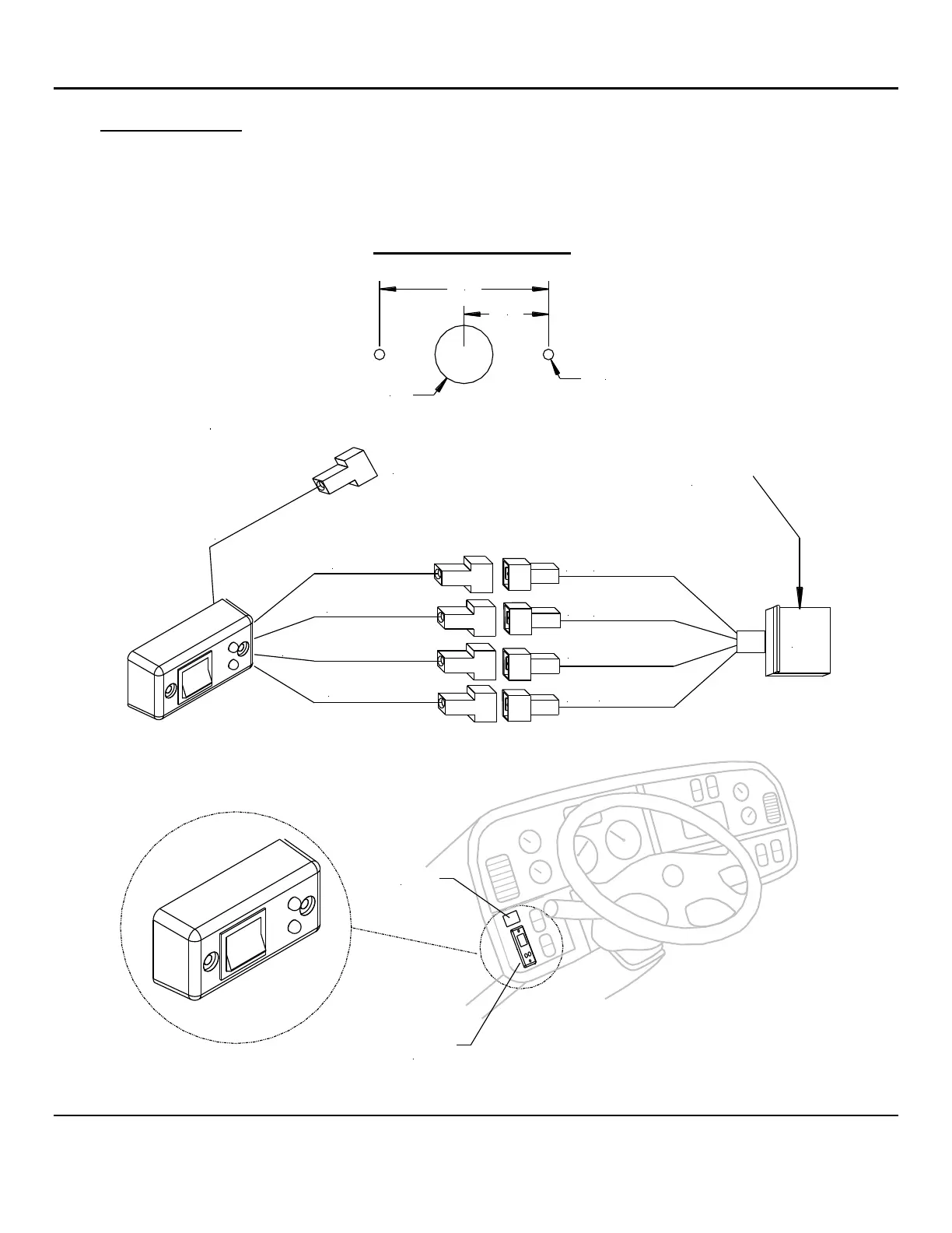
2. Switch Installation: Route the other end of the harness to the cab’s dashboard. Position the switch where
it is visible and accessible by the user from outside the cab. Use the mounting hole pattern below and
mount the switch with the provided screws, Fig. 22. Wire the switch and harness per diagram. Test the
switch. After testing and making sure the switch is functioning properly, place the decal near the switch,
Fig. 23.
ø 11/16"
2X
ø 1/8"
No Use
Blue #4
Black
Black
(-)Yellow/Green
Yellow/Green (-)
#2
#4
#1
Red #2
J11
Black
Blue (3)
White #1
J11 From
Control
Board
Decal
Cab
Shutoff
Switch
Mounting Hole Pattern
1.00"
2.00"
Fig. 22
Fig. 23

Table of Contents

Related product manuals