T5 Flare Gas Transducer Installation Guide 37
Chapter 3. Installing the Transducer Assemblies
3.3 Mounting the Bias 90 Insertion Mechanism/Transducer Assembly (cont.)
3. Identify the upstream and downstream nozzles as follows:
• For a
Standard Velocity Range
application, the upstream and downstream nozzles are interchangeable,
because the system is bi-directional.
• For an
Extended Velocity Range
application, the system is not bi-directional. Note which nozzle is
designated as upstream and which is designated as downstream on the pipe. Then, identify the
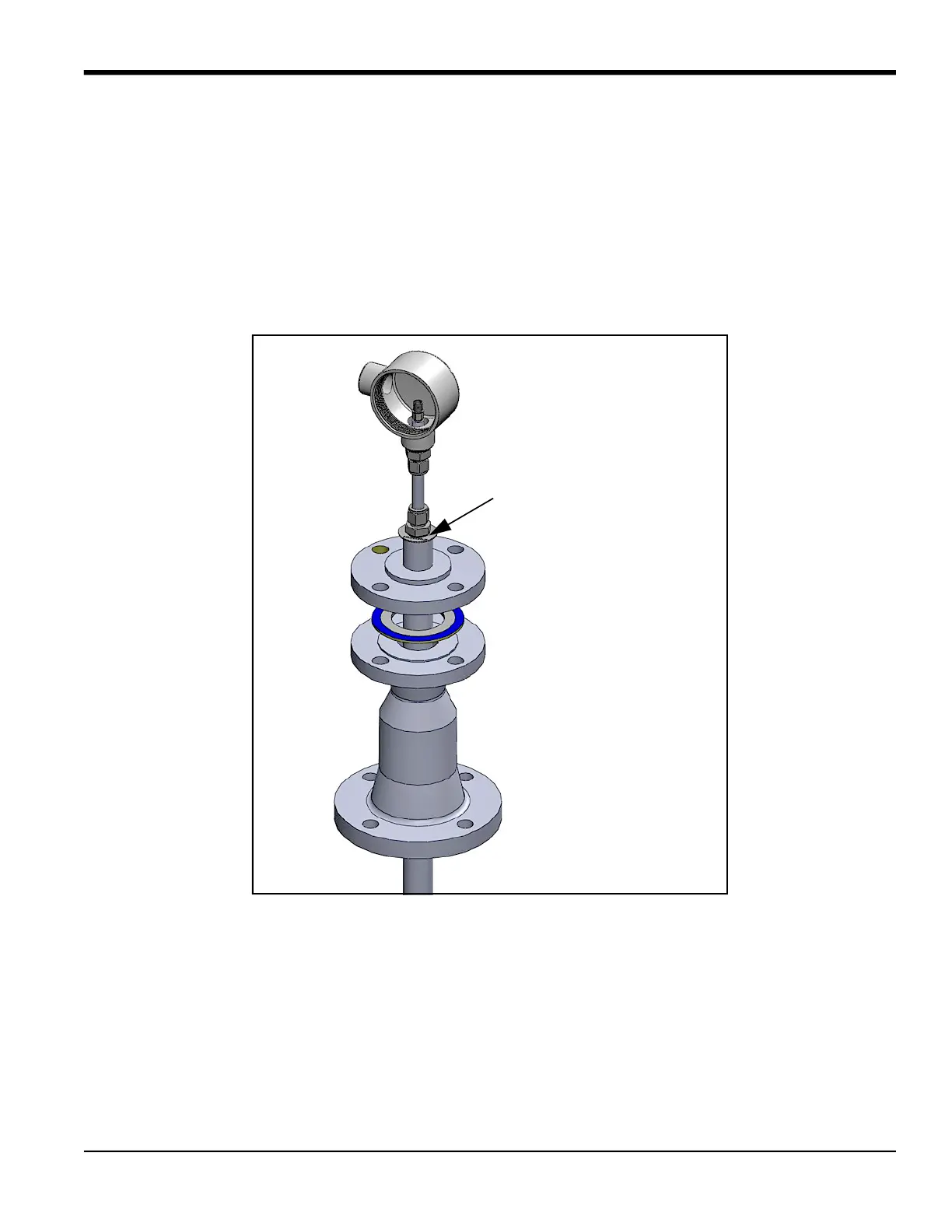
upstream and downstream insertion mechanism assemblies. The downstream assembly is labeled with
a ring marked Downstream at the end of the assembly near the junction box (see the figure below).
4. Proceed with either the upstream or downstream assembly.
5. Lift the insertion mechanism by the barrel and place the insertion mechanism on the isolation valve.
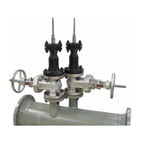
Downstream Transducer Assy.
Identification Ring
(on Extended Range Version)
 Loading...