T5 Flare Gas Transducer Installation Guide 47
Chapter 3. Installing the Transducer Assemblies
3.7 Mounting the Tilted 45 Insertion Mechanism/Transducer Assembly (cont.)
2. Check and make sure the isolation valves are securely installed with gaskets and hardware. Then, place a gasket
on the face of each isolation valve (see either
Figure 14
below or
Figure 15 on page 48
).
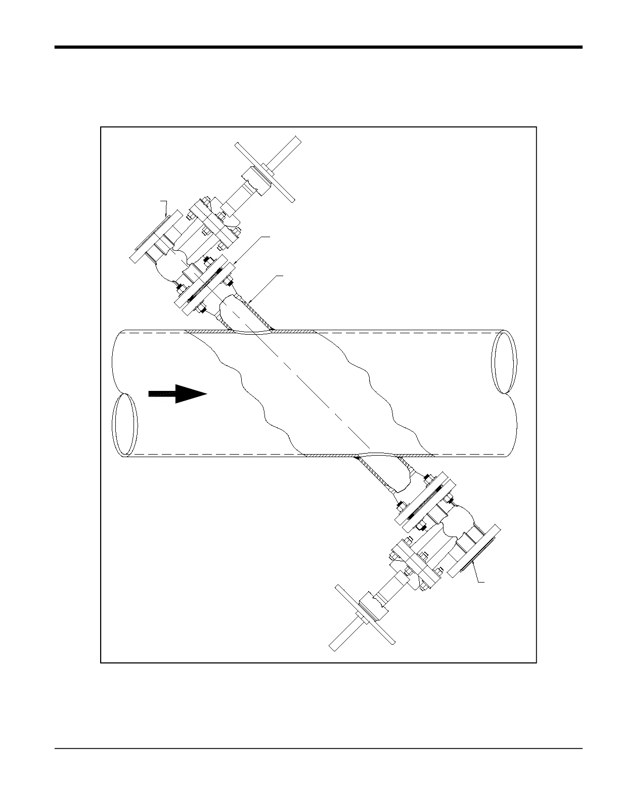
Figure 14: Standard Velocity Range Assembly
2 PLACES; REF ONLY
3 INCH SCH 80 PIPE NOZZLE
3 INCH 150 LB, RF WELDING NECK FLANGE
2 PLACES; REF ONLY
FLOW
TRANSDUCER PORT
UPSTREAM
TRANSDUCER PORT
DOWNSTREAM
GASKET
GASKET
 Loading...