38
11.3.4 Air Purging of the Piping and Indoor
The remaining air in the Refrigeration cycle which contains moisture may cause malfunction on the compressor.
1 Remove the caps from the 2-way and 3-way valves.
2 Remove the service-port cap from the 3-way valves.
3 To open the valve, turn the valve stem of 2-way valve counter-clockwise approx. 90° and hold it there for ten
seconds, then close it.
4 Check gas-leakage of the connecting portion of the pipings.
o For the left pipings, refer to item 4(A).
Lo
Hi
4(A). Checking gas leakage
for left piping
1) a.
Connect the
manifold gauge to
the service port
of 3-way valve.
b.
Measure the
pressure.
2) a.
Keep it for 5-10
minutes.
b.
Ensure that
the pressure
indicated on the
gauge is the
same as that of
measured during
the fi rst time.
Following Result of
the right side piping.
OPEN
CLOSE
Gas side
No leakage found
Locate and repair leak
Re-tighten the connecting
portion with torque
wrenches.
6. To purge the air, push the pin on
the service port of 3-way valve for
three second using with a hexagonal
wrench and set it free for one minute.
Repeat this three times.
7.
Set the both 2-way and 3-way valves to open position with the
Hexagonal wrench for the unit operation.
Control
board
cover
Gas side
Liquid side
2-way valve (open)
Cap
3-way valve (open)
Hexagonal wrench
Service port cap
Terminal board
Over
5 mm
5. To open 2-way valve again,
turn the valve stem counter-
clockwise until it stop.
To indoor unit
Liquid side
Indoor unit
Close
Close
Outdoor unit
Result
Leakage found
Leakage persists
Leakage ceased
Leakage ceased
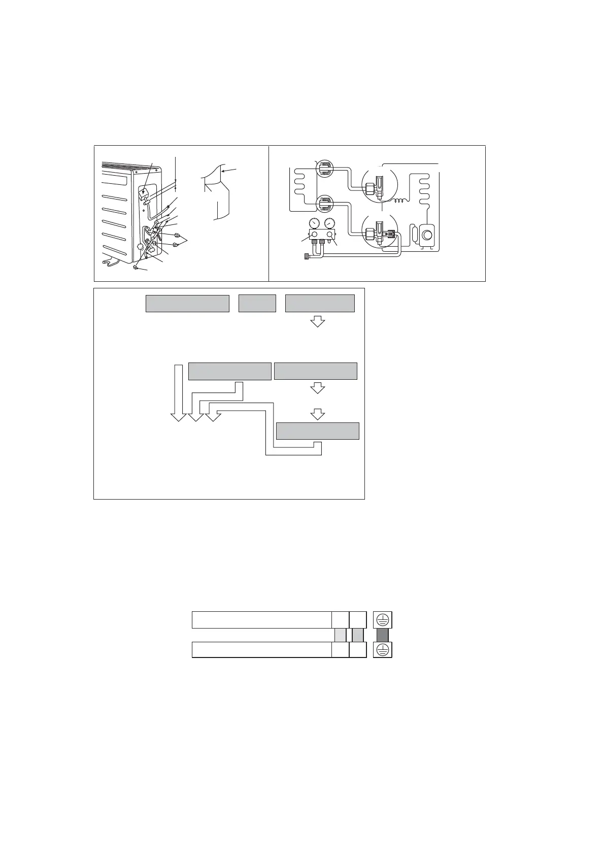
11.3.5 Connect the Cable to the Outdoor Unit
1 Remove the control board cover from the unit by loosening the screw.
2 Connection cable between indoor unit and outdoor unit shall be approved polychloroprene sheathed
3 x 1.5 mm
2
(1.5HP) or 3 x 2.5 mm
2
(2.0 ~ 2.5HP) flexible cord, type designation 60245 IEC 57 or heavier
cord. Do not use joint connection cable. Replace the wire if the existing wire (from concealed wiring, or
otherwise) is too short.
Terminals on the outdoor unit 1 2
Colour of wires
Terminals on the indoor unit 1 2
3 Secure the cable onto the control board with the holder (clamper).
4 Attach the control board cover back to the original position with screw.
5 For wire stripping and connection requirement, refer to instruction 11.2.4 of indoor unit.