1-12-1-2-22
1
(4) Wiring the Panel for Cassette
1) Open the cover of the electrical component box for
the indoor unit control PCB.
2) Connect the 22P connector (white) and 6P connector
(white) from the panel for cassette to the connector on
the indoor unit control PCB in the unit electrical
component box.
In this case, expose the cutout section of the tube for
the wiring protection to the outside from the electrical
component box and fix it with the clamper attached to
the electrical component box.
Insert connector lock facing PCB edge until it is
locked in place. (If not connected completely, the
Auto Flap will not operate and “P09” is displayed
on the remote controller. When the connector
plugged in the wrong direction, parts on the PCB
may be damaged.)
Check that the wiring connector is not caught
between the electrical component box and the
cover.
Check that the wiring connector is not caught
between the unit and the panel for cassette.
Lid of electrical component box
(5) How to Attach the Corner & Air Intake Grille
A. Attaching the corner cover
1) Check that the safety strap from the corner cover is
fastened to the panel for cassette pin, as shown in the
figure below.
2) Use the supplied screws to attach the corner cover to the
panel for cassette.
Pin
Place the corner cover
so that the 5 tabs fit into
the holes in the panel
for cassette. Then
fasten it in place with
the supplied screws.
Supplied screw
B. Attaching the air intake grille
To install the air intake grille, follow the steps for
“Removing the grille” in the reverse order. By rotating the
air intake grille, it is possible to attach the grille onto the
panel for cassette from any of 4 directions. Coordinate the
directions of the air intake grilles when installing multiple
units, and change the directions according to customer’s
requests.
When attaching the air intake grille, be careful that the
flap lead wire does not become caught.
Be sure to attach the safety strap that prevents the air
intake grille from dropping off to the panel for cassette
unit as shown in the figure below.
With this panel for cassette, the directions of the air
intake grille lattices when installing multiple units, and the
position of the label showing the company name on the
corner panel, can be changed according to customer’s
requests, as shown in the figure below. However, the
wireless signal receiver can only be installed at the
refrigerant-tubing corner of the ceiling unit.
Hole of panel for cassette hook
Refrigerant tube side
Optional wireless receiver kit
* This position is only possible for
installation.
Corner cover installation position
marked with the Panasonic Logo at
shipment.
* Installation possible at every corner
Electrical component box
ECONAVI sensor
*This installation position cannot be moved to another location.
Can be installed
rotated 90°
Locations of air intake grille hinges at
shipment
* The grille can be installed with these
hinges facing in any of 4 directions.
Drain pipe side
Hook that prevents the grille from dropping
Screws (×2)
Cutout section of the tube
for wiring protection
22P (white)
22P (white)
6P (white)
(For ECONAVI )
6P (white)
(For ECONAVI )
Wiring diagram
(Direction that the unit
faces has been changed to
facilitate explanation.)
Connector
Lock
Others
Setting No.
(1)
Remote controller
setting data
Item code 5d
0001
Contents &
optional parts name
Air-flow blocking kit
(for 3-way air flow)*
2
1
High-ceiling setting 1*
2
(3) 0003
High-ceiling setting 2*
2
(6)
Air-flow blocking kit
(when a duct is
connected.)
0006
Air-flow blocking kit
(for 2-way air flow)*
2
oN gnittes tnereffid ni strap lanoitpo gnisu nehW 1* . in
combination with multiple units, conform it to the larger
setting No.
)m( thgieh gnilieC 2*
(1) Checking After Installation
1) Check that there are no gaps between the unit and the
panel for cassette, or between the panel for cassette
and the ceiling surface.
* Gaps may cause water leakage and condensation.
.detcennoc yleruces si gniriw eht taht kcehC )2
ton lliw palf otua eht ,detcennoc yleruces ton si ti fI *
operate.
(“P09” is displayed on the remote controller.)
In addition, the water leakage and condensation may
occur.
(2) Operating the Wireless Remote Controller
For details of installation, refer to the section “Wireless
Signal Receiver” in the supplied installation instructions.
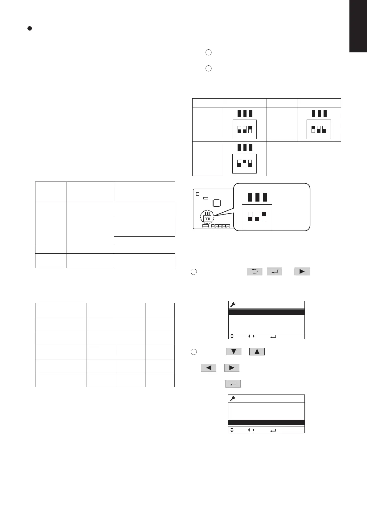
(3) Selecting DC Fan Motor Tap (4-Way Cassette)
Check the optional parts accordingly in the following
table.
Table for DC Fan Motor Tap Settings*
Indoor unit type
Standard
3.6
High-ceiling setting 1
(factory setting)
4.3
High-ceiling setting 2 5.0
4.7
Air-flow blocking kit
(for 3-way air flow)
5.0
3.0
3.3
3.6
3.8
4.2
S-3650PU3E S-6071PU3E S-1014PU3E
2.7
3.2
3.5
Air-flow blocking kit
(for 2-way air flow)
3.8
4.2
eht no gnittes nehW )1 P.C. Board
Setting No. DIP switch
<Procedure>
Stop the system before performing these steps.
1
oc xob tnenopmoc lacirtcele eht nepO ver, then
check the indoor unit control PCB.
2
lortnoc tinu roodni eht no hctiws PID eht egnahC
Setting No. DIP switch
(1)
PCB in accordance with the setting number which
was confirmed in “Table for DC Fan Motor Tap
Settings”.
TP6
TP3
TP1
ON
1 2 3
(6)
ON
TP6
1 2 3
TP3
TP1
(3)
ON
TP6
1 2 3
TP3
TP1
<Procedure of CZ-RTC5B>
Stop the system before performing these steps.
1
Keep pressing the
, and buttons
simultaneously for 4 or more seconds.
The “Maintenance func” screen appears on the LCD
display.
2
Press the or button to see each menu.
press the
button.
If you wish to see the next screen instantly, press the
or button.
Select “8. Detailed settings” on the LCD display and
The “Detailed settings” screen appears on the LCD display.
Maintenance func
Sel.
20:30 (THU)
Page [ ] Confirm
1. Outdoor unit error data
2. Service contact
3. RC setting mode
4. Test run
Maintenance func
6. Servicing check
5. Sensor info.
Sel.
20:30 (THU)
7. Simple settings
8. Detailed settings
Page [ ] Confirm
TP6
TP3
TP1
1
ON
2 3
TP6
TP3
TP1
1 2 3
SW001
Indoor unit control PCB
Setting example
1: OFF
2: OFF
ON
3: ON
SM830281-00_欧州向け R32シングル TD&SM.indb 22 20/01/09 14:59:59