22
2-3-2-6
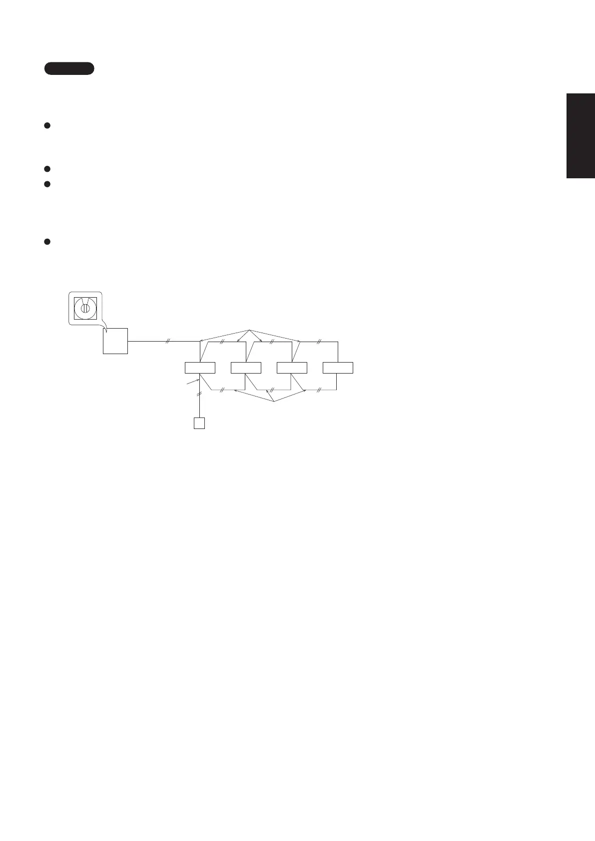
2-6-2. Address Setting : 2-LINE CONNECTION
NOTE
The displays of the earth, outdoor unit power supply wiring and earth leakage circuit breaker are omitted.
2-6-2-1. Basic connection 1 : Single type and simultaneous multiple operations
1 - 1 1 - 2 1 - 3 1 - 4
Simultaneous multiple operations: It is possible to operate maximum 4 (double-twin) indoor units within
one outdoor unit. (Only specified indoor unit combination.
Independent operation is not possible by connecting an individual remote controller.)
It is not necessary to make setting of the refrigerant system address.
When turning on all indoor and outdoor units, the auto address will start.
It takes maximum 10 minutes. LED1 and LED2 of outdoor unit control PCB blink alternately during auto
address setting.
When finished, LEDs go off.
When the auto address setting is completed, wait at least 1 minute and 30 seconds.
Then start the operation.
0
Inter-unit control wiring
Outdoor unit
Simultaneous multiple (double-twin) operations
Indoor unit
Remote control
wiring
System address rotary switch
(Factory shipment: “0”)
Remote controller
Remote control wiring
for group control
2-6-1. Basic wiring diagram
2-6. System Control
System control refers to the link wiring connection for control of simultaneous-operation multi systems,
group control, and main-sub remote controller control.
Fig. 2-3-2-1
Be careful to avoid miswiring when connecting the wires.
(Miswiring will damage the units.)
(for 3-phase Outdoor unit)
(Wiring procedure)
Type U3 (Example of TWIN type)
(1) Connect the remote controller to the indoor unit remote controller wiring terminal plate (R1, R2).
(Remote controller wiring)
(2) Connect the indoor units (U1, U2) and the outdoor units (U1, U2). Connect the other outdoor units and indoor
units (with different refrigerant systems) in the same way. (Inter-unit control wiring)
Connect the remote controller communication wiring to the indoor units (R1, R2) for each refrigerant system.
(Remote controller wiring)
(3) Connect the remote controller communication wiring (2 wires) from the remote controller wiring terminal plate
(R1, R2) on the indoor unit
(unit where the remote controller is connected)
to the remote controller terminal plates
(R1, R2) on the other indoor units. (Remote controller communication wiring)
(4) Turn ON both the indoor and outdoor unit power and perform automatic address setting from the remote
controller. (For the automatic address setting procedure, see 2-6-3.)
NOTE
* Be sure to use the indoor unit temperature sensor (body sensor) when using this control. (Status at shipment.)
1
2
Ground Ground
WHT BLK
U1
U2
R1
R2
Indoor
unit
U1
U2
R1
R2
Indoor
unit
(Optional)
Wired remote
controller
Leakage breaker Leakage breaker
Inter-unit control wiring
U1
U2
L1 L2 L3
N
System address rotary switch
(Set to “0” at the time of shipment.)
Outdoor unit
Leakage breaker
Ground
Remote controller wiring
L/1
N/2
3
L/1
N/2
3
SM830281-00_欧州向け R32シングル TD&SM.indb 6 20/01/09 15:02:49