22
2-3-2-8
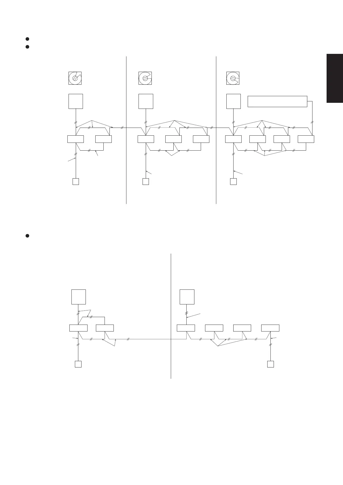
2-6-2-3. Basic connection 3 : Example of link wiring (when using integrated control system)
1 - 1 1 - 2 2 - 1 2 - 2 2 - 3 3 - 1 3 - 2 3 - 3 3 - 4
Before turning on the power (earth leakage circuit breaker), make refrigerant system auto address setting.
Make indoor unit auto address setting. (See 2-6-4.)
3
2
1
Refrigerant system 1 Refrigerant system 2
System address
Refrigerant system 3
rotary switch
Remote control wiring
for group control
Remote control wiring
for group control
Twin Triple Double-twin
Remote control
wiring for group
control
Unit No.1
Outdoor unit
Indoor unit
Remote controller Remote controller
Remote control
wiring
Remote controller
Remote control wiring Remote control wiring
Set to 1 Set to 2
Unit No.2
Set to 3
Unit No.3
Integrated control system
Inter-unit control wiring
Inter-unit control wiring
Inter-unit control
wiring
* It is possible to connect maximum 8 indoor units with one remote controller.
2-6-2-4. Basic connection 4 : Group control with 3-LINE CONNECTION unit
1 - 1 1 - 2 2 - 1 2 - 2 2 - 3 2 - 4
* Remote control wiring is necessary in all indoor units.
Make auto address setting following the procedure “2-6-2-2. Basic connection 2”.
2-LINE CONNECTION system 1
Set the system address to 1. Set the system address to 2.
3-LINE CONNECTION system 2
Inter-unit control wiring
Unit No.1
Outdoor unit
Connection cable between
outdoor and indoor unit
Unit No.2
Remote control wiring
for group control
Twin
Indoor unit
Double-twin
Remote control wiring for
group control
Remote controller Remote controller
Remote control
wiring
Remote control
wiring
Select the settings for the
system address by the
remote controller. (See 2-6-3.)
Select the settings for the
system address by the
remote controller. (See 2-6-3.)
SM830281-00_欧州向け R32シングル TD&SM.indb 8 20/01/09 15:02:49