22
2-3-2-9
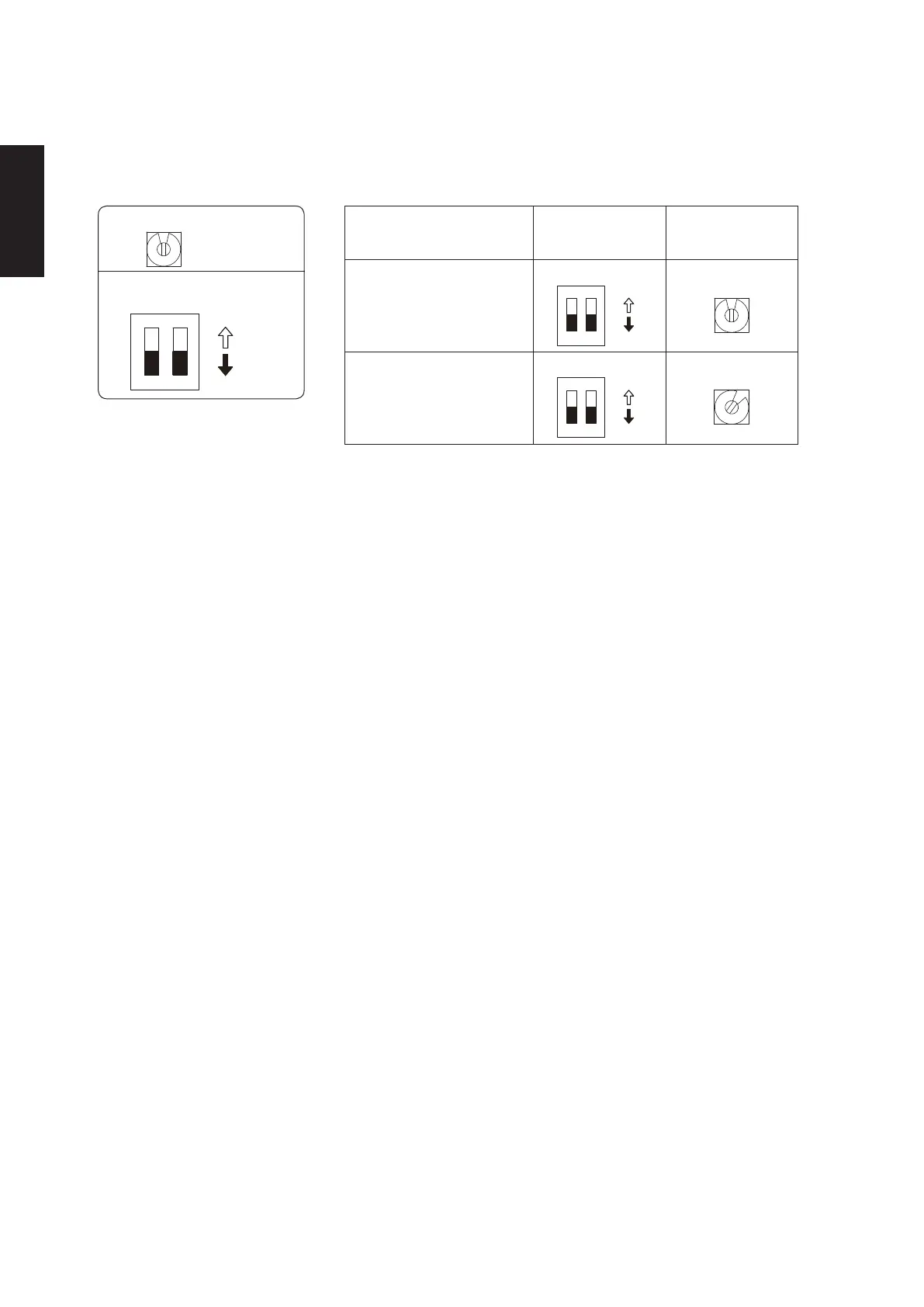
System address rotary switch
0
2-6-2-5. Setting the Outdoor unit system addresses
For basic wiring diagram (Set the system address: 1)
Outdoor unit control PCB
System address rotary switch
(Set to “0” at time of shipment)
System address
1 2
10
20
DIP switch
ON
ON
OFF
System address No.
System address
10 digit
(2P DIP switch)
0 Auto address
(Setting at shipment = “0”)
System address
1 place
(Rotary switch)
1
2
Both OFF
ON
ON
OFF
“0” setting
0
1 (If outdoor unit is No. 1)
1
2
Both OFF
ON
ON
OFF
“1” setting
1
SM830281-00_欧州向け R32シングル TD&SM.indb 9 20/01/09 15:02:49