1-4-1-2-1
1
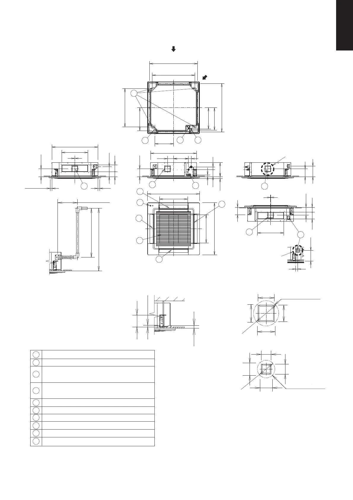
* Necessary to attach duct connecting flange (field supply)
<Filter dimension>
520 x 520 x 15
The length of the suspension bolts
should be selected so that there is
a gap of 30 mm or more below the
lower surface of the ceiling (18 mm
or more below the lower surface of
the main unit), as shown in the
figure at right. If the suspension
bolt is too long, it will contact
the ceiling panel and the unit
cannot be installed.
Raise dimension of drain tube
unit: mm
View X
View XX
X
Z
Y
Detailed view Z
Detailed view Y
Over
30
Over 18
122
∅113
80
64
80
64
4 - M4
Tapping screw holes
∅162
115
105
105
115
4 - M4
Tapping screw holes
Less than 666
Less than 850
Less than 300
Less than 35Less than 35
256
272110
840
143
32
127
50
51
33.5
2
2
2
7
4
3
5
8
1
6
7
9
7
7
2
10
950
515
515
950
340
(410)
(390)
418
124
90
134
143
2
480
90 124
184
2
480
840
143
143
192
(192)
35
860~910
780
(Ceiling opening dimensions)
(Suspension bolt pitch)
860~910
(Ceiling opening dimensions)
XX
(Air intake)
(Air intake)
700
(Suspension bolt pitch)
(A) Indoor Units: 4-Way Cassette Type
S-3650PU3E, S-6071PU3E
1-4. Dimensional Data
1
2
3
4
5
6
7
8
9
10
Discharge outlet
Air intake
Drain tube connection port VP25 (outer dia. ø32)
ECONAVI sensor (CZ-KPU3A or CZ-KPU3AW)
Discharge duct connection port (ø150)
Power supply port
Suspension bolt hole (4-12×30 elongated hole)
Fresh air intake duct connection port (ø100) *
Refrigerant tubing joint (liquid tube)
Refrigerant tubing joint (gas tube)
S-3650PU3E : ø12.7 (flared)
S-6071PU3E : ø15.88 (flared)
S-3650PU3E : ø6.35 (flared)
S-6071PU3E : ø9.52 (flared)
SM830281-00_欧州向け R32シングル TD&SM.indb 1 20/01/09 14:59:23