EasyManua.ls Logo

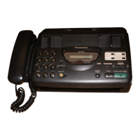
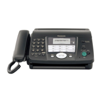
Panasonic KX-FT21BX

Panasonic KX-FT21BX
206 pages
To Next Page IconTo Next Page
To Previous Page IconTo Previous Page
Loading...
- 41 -
KX-FT21LA
TROUBLESHOOTING GUIDE
Connect the unit to the
loop simulator.
Switch : TX side T-R
Connect the oscilloscope.
Modem test start
Are four signals output
at the Tip-Ring?
Connect the PBX and
TEL. line and go off-hook.
Check the trace
between pins 3 of
IC5 and Tip-Ring.
Is the signal at pin 45
of IC5 dial tone input?
Replace IC5.
Replace IC5.
Check the trace
between T1 and pin
15 of IC5.
Is the signal at pins
3 of IC5 output?
Check the solder at
pins 1~16 of IC5.
Check the solder at
pins 70~81 of IC1.
OK
OK
Replace IC1.
NG
Check the solder at
pins 1~16 of IC5.
Check the solder at
pins 70~81 of IC1.
OK
OK
Replace IC1.
NG
4 The unit can copy, but cannot transmit/receive.
YES
YES
YES
NO
NO
NO
(TEST CODE NO. 554)

Table of Contents

Related product manuals