EasyManua.ls Logo

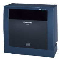
Panasonic KX-NCP500 - System Connection Diagram

Panasonic KX-NCP500
156 pages
To Next Page IconTo Next Page
To Previous Page IconTo Previous Page
Loading...
1.1.2 System Connection Diagram
KX-T7600 KX-T7600
Doorphone & Door Opener
BGM/Music On Hold (MOH)
Pager/
Speaker
Voice Processing
System
KX-T7636/
KX-T7633
Remote PC
PC
Printer
Router
Trunk (Telephone Company Lines)
Analogue/BRI/PRI/T1/E1
Pure IP-PBX
PC
CSPS
Wireless Phone
Fax Machine
PC
USB
APT
DPT
ISDN Telephone
Amplifier
SLT
DSS Console
DSS Console
External Sensor/
External Relay Device
IP-PT
IP Softphone, CA
*
3
Client PC
PC
PC
CTI Server
SIP Extension
Private
IP Network
ITSP
*
1
Network
DCE
*
2
(e.g., ADSL
Modem)
WAN
KX-DT346/
KX-DT343
PC
USB
KX-DT300
KX-DT300
IP-CS PS
*1
ITSP: Internet Telephony Service Provider
*2
DCE: Data Circuit Terminating Equipment
*3
CA: Communication Assistant
Installation Manual 19
1.1.2 System Connection Diagram

Table of Contents

Other manuals for Panasonic KX-NCP500

Related product manuals