No. SX-DSV03335 - 47-
R2.0 Industrial Device Solution Business Unit, Panasonic Corporation
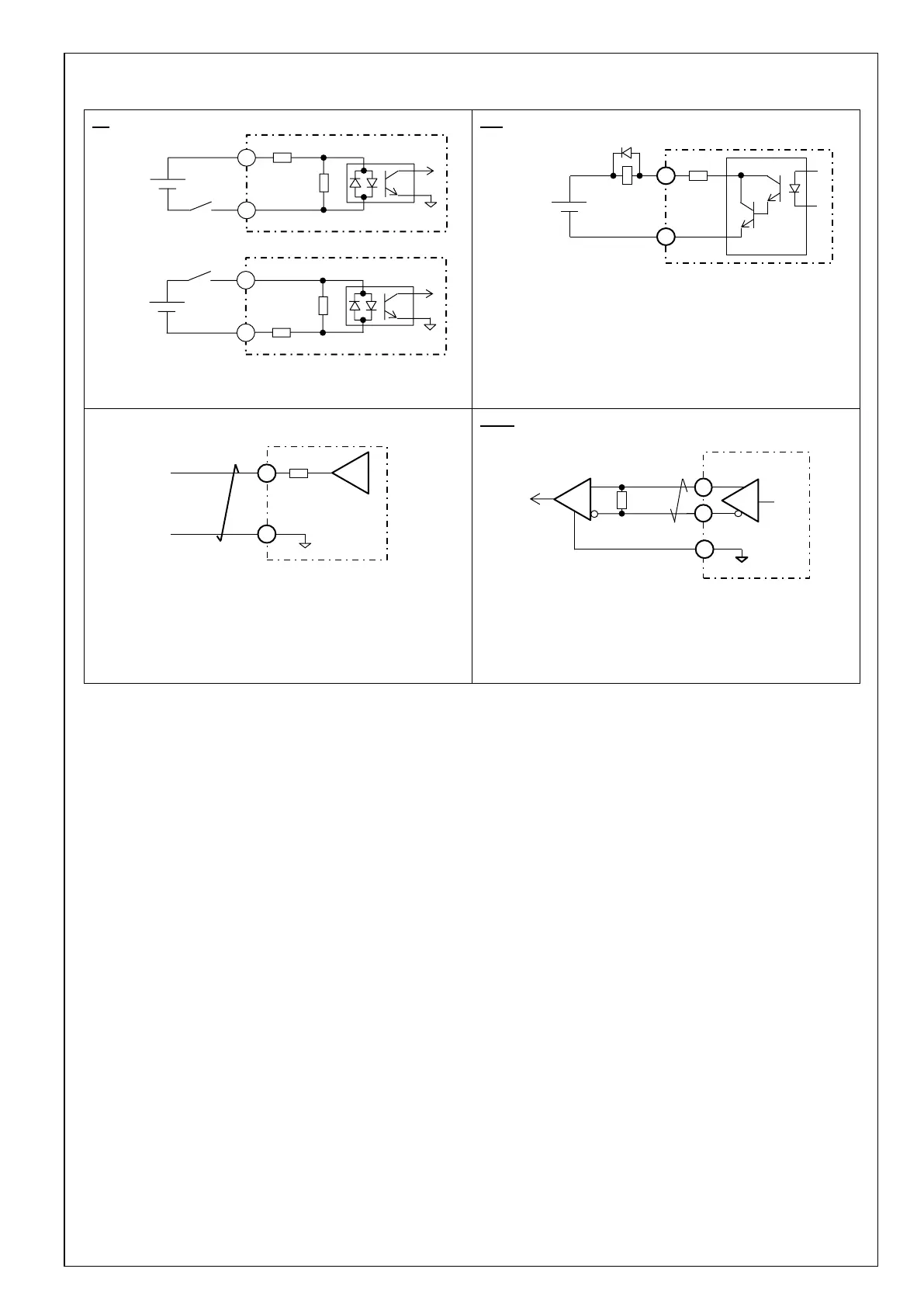
7-9 Input/output signal interface
i-1
S: (X3) 3,5pin / (X4) 5,7,8,9,10,11,12,13pin
P: (X3) 4,6pin / (X4) 6pin
o-1
+: (X3) 8pin / (X4) 1,3,25pin
-: (X3) 7pin / (X4) 2,4,26pin
Note) When driving the relay directly, install a diode in parallel
with the relay in the direction shown above.
Ao-1
S: (X7) 1,2pin
G: (X7) 3pin
The output signal amplitude is ±10 V.
Do-1
+: (X4) 17,20,21pin
-: (X4) 18,19,22pin
G: (X4) 16pin
Connect a terminating resistor (approx. 330 Ω) between the line
receiver inputs.
+
GND
G
-
Twisted pair
Equivalent of
AM26C32
P
S
1 kΩ
4.7 kΩ
V
DC
12-24 V
S
P
1 kΩ
4.7 kΩ
V
DC
12-24 V
or