No. SX-DSV03335 - 50-
R2.0 Industrial Device Solution Business Unit, Panasonic Corporation
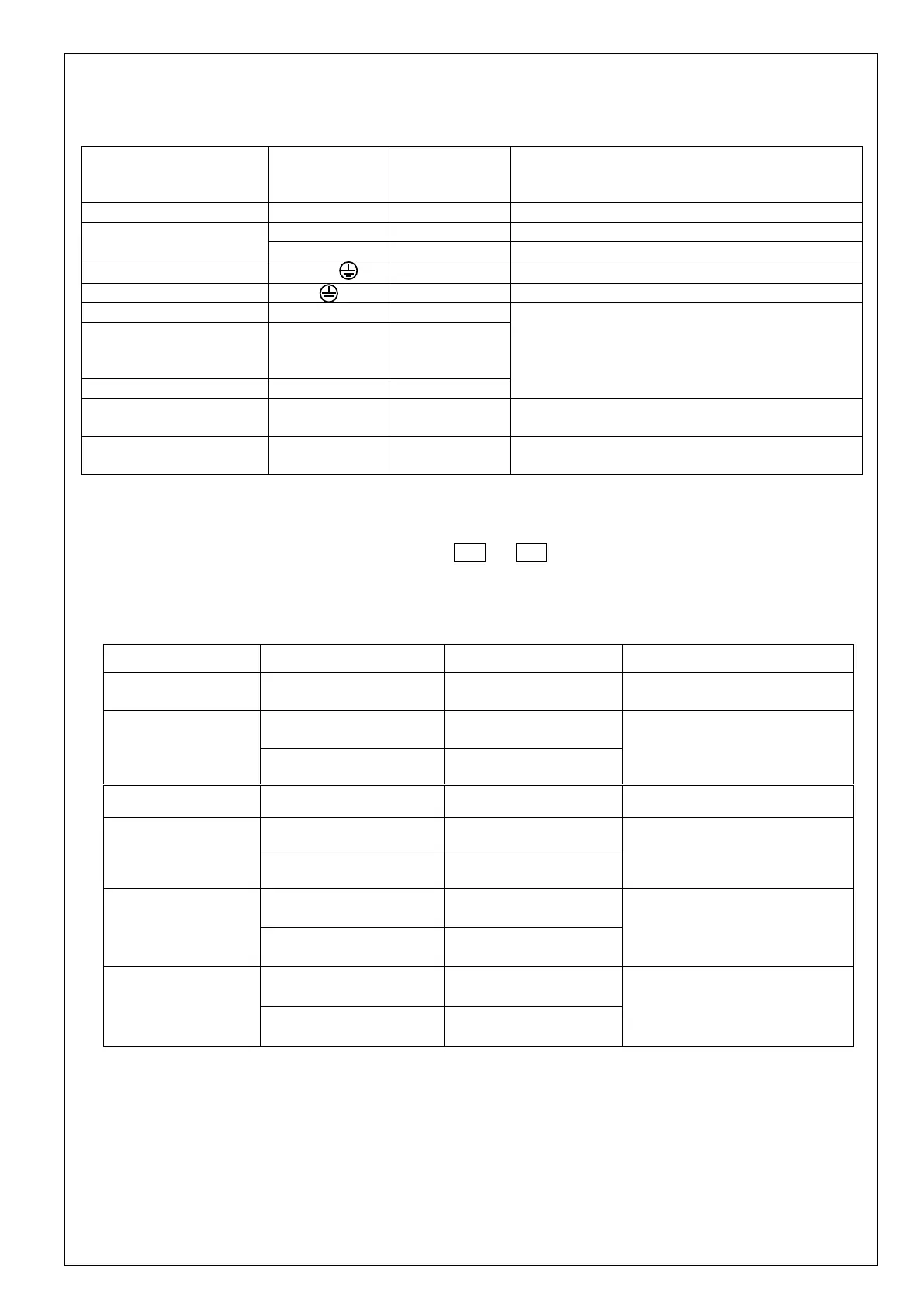
8. Wiring and system configuration
8-1 Wire rods used and maximum wiring length
Maximum
cable length
(Note 1)
Refer to chapter 14 “specification for each models”
Refer to chapter 14 “specification for each models”
Refer to chapter 14 “specification for each models”
Refer to chapter 14 “specification for each models”
Refer to chapter 14 “specification for each models”
Shielded twisted-pair cable
Core cable 0.18 mm
2
or more
Feedback scale
connection
(Note 3)
Safety connection
(Note 3)
Core cable 0.18 mm
2
or more
Note 1) The above wiring length is the maximum value under the evaluation environment of Panasonic.
It does not guarantee the operation under the working environment of the customer.
Note 2) Refer to “8-3-4 Connection to connectors X2A and X2B”.
Note 3) Only multi function type is supported.
8-2 Cable side connector
Solder plug
(soldered type)
Japan Aviation
Electronics Industry
(JAE)
Use the above connector or equivalent.
Note 1) Correspond to Size G only.