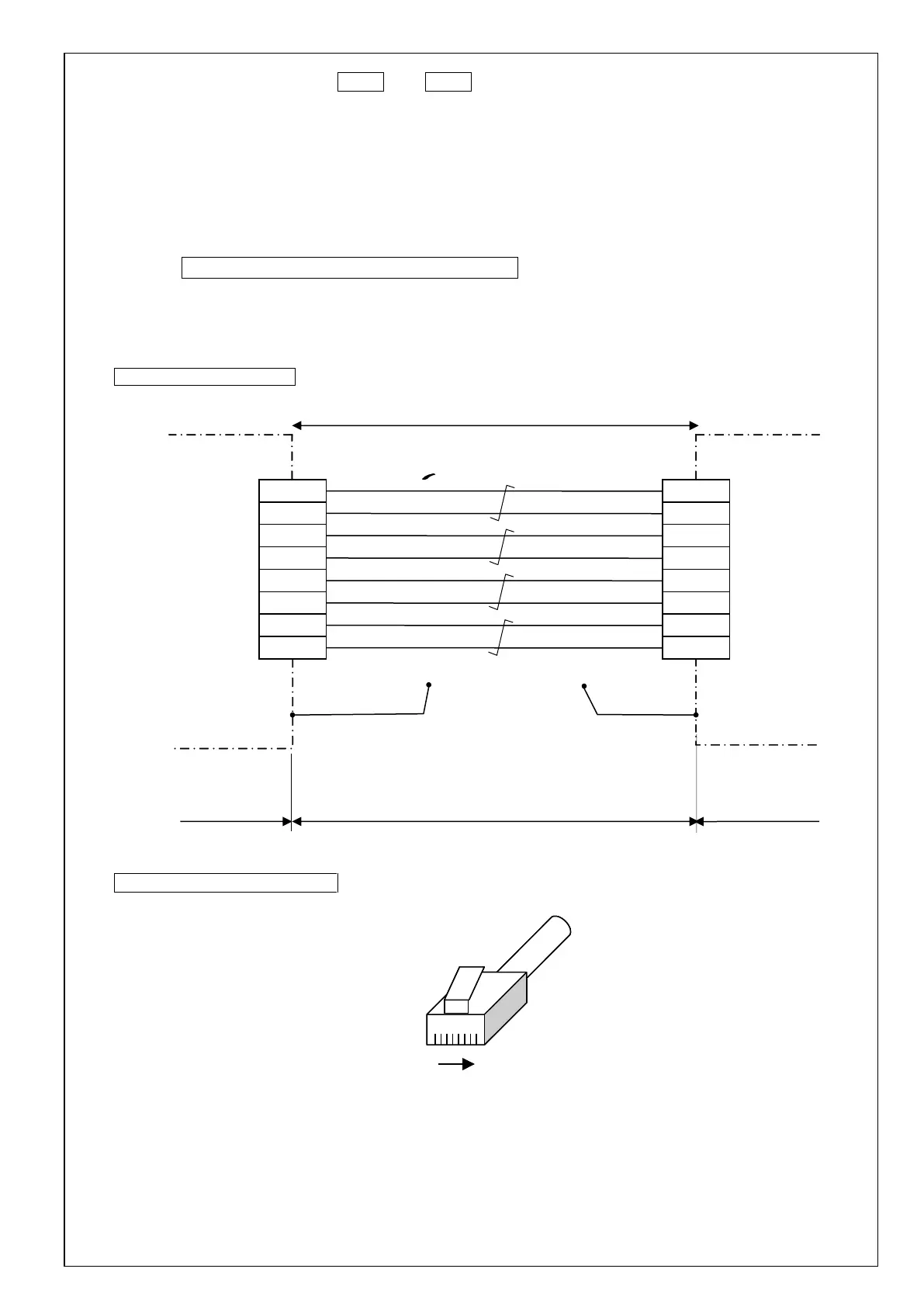
8-3-4 Wiring to connectors X2A and X2B
[1] Use a shielded twisted pair (STP) cable in conformance with category 5e of SIA/EIA-568 or higher.
[2] If both ends of the shield are not grounded, the EMC characteristic will deteriorate.
When installing connector plug on both ends of shielded cable, positively connect the shield to the metallic plug shell.
[3] For colors of wire and matching connector terminals, refer to TIA/E1A568B (see figure below).
Terminals 3 and 6 are for signal wire. Connect wire to 3 terminal pairs on the connector: 1–2, 4–5 and 7–8.
[4] When using 2-pair wire in place of 4-pair wire, use terminals 1–2 and 3–6 and leave terminals 4–5 and 7–8 on
connector unconnected.
[5] The wiring length of the communication cable should be within the range that satisfies the following conditions.
[6] Cable specifications including flexural property, temperature range, and materials used for covering are different
according to manufacturers.
Select the cable according to the working conditions of the customer.
Select the cable for movable application according to your operating condition.
Connection of X2A / X2B
Terminal layout of the RJ45 plug