Do you have a question about the Panasonic PT-AX200U and is the answer not in the manual?
Basic safety rules for servicing the projector, including no modifications.
Procedure and circuit for measuring leakage current to ensure user safety.
Safety measures for handling the projector lamp, including UV radiation and heat.
Step-by-step guide to access the Extended Options menu.
Description of available functions within the EXT OPTION menu for service.
How to exit the Extended Options menu.
Instructions on how to activate the self-check diagnostic mode.
Explanation of the self-check mode's display elements and their meanings.
How to exit the self-check mode.
Steps to access the mode for minimizing flicker after component replacement.
Details on the adjustment display and controls for flicker minimization.
How to save settings and exit the flicker adjustment mode.
How to physically connect the projector to a PC via the serial port.
Pin assignments and signal descriptions for the projector's serial connector.
Required communication parameters for PC control via serial interface.
Structure of data transmission between PC and projector for control.
List of commands for controlling projector functions and querying status.
Specifications for serial communication cables and adapters.
Cable specifications for connecting to signal selectors.
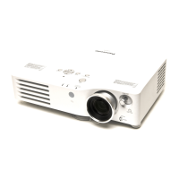
Identifies the location of main electrical and optical parts within the projector.
Procedures for removing external covers and major internal modules like boards.
Steps for removing and replacing optical parts like lamp, LCD panels, and lens.
Procedures for replacing specific components like polarizers and PBS arrays.
General procedure, safety cautions, and preparation for all adjustments.
Detailed steps for adjusting the convergence of the LCD panels.
Procedure for adjusting the projector's lighting area and reflectors.
Information on computer-aided adjustments, including software operation and data transfer.
Procedure for fine-tuning flicker settings using software.
Procedure for adjusting RGB input levels via software.
A series of diagnostic flowcharts covering various projector malfunctions and their solutions.
First part of the diagram showing how major modules interconnect.
Second part of the diagram showing module interconnections.
Block diagram illustrating the projector's power supply system.
First part of the block diagram showing signal processing flow.
Second part of the block diagram showing signal processing flow.
Electrical schematic for the PT-AX200U model.
Electrical schematic for the PT-AX200E model.
Crucial safety warnings regarding critical components in shaded schematic areas.
Component layout and foil side views of the A-P.C.Board.
Component layout and foil side views of R-P.C.Board and S-P.C.Board.
First part of the exploded view showing parts locations.
Second part of the exploded view showing parts locations.
Third part of the exploded view showing parts locations.
| Projection distance | 1.2 - 12.4 m |
|---|---|
| Vertical scan range | 50 - 87 Hz |
| Horizontal scan range | 30 - 70 kHz |
| Projection technology | LCD |
| Screen size compatibility | 40 - 200 \ |
| Aspect ratio | 16:9 |
| RS-232 ports | 1 |
| Dimensions (WxDxH) | 395 x 300 x 112 mm |
| Power requirements | AC 100 - 240 V 50 Hz/60 Hz, 3.5 A - 1.5 A |
| Connectivity technology | Wired |
| F-number (relative aperture) | 1.9 |
| Lamp type | UHM |
| Lamp power | 220 W |
| Light source type | Lamp |
| Focus | Manual |
| Focal length range | 21.7 - 43.1 mm |
| Certification | UL60950-1, FCC Class B, C-UL, ICES-003 |
| Dot clock scanning frequency | 150 MHz |
| Serial interface type | RS-232 |
| Power consumption (typical) | 290 W |
| Operating temperature (T-T) | 0 - 40 °C |
| Operating relative humidity (H-H) | 20 - 80 % |
| Placement | Ceiling |
| Market positioning | Home cinema |
| Weight | 4900 g |
|---|