DIA-1
SECTION 4 SCHEMATIC DIAGRAM
CONTENTS
Schematic Diagram
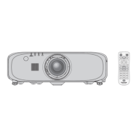
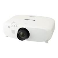
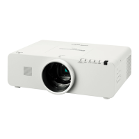
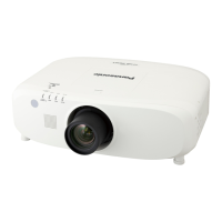
Model No. PT-EZ770Z / PT-EZ770ZL
PT-EW730Z / PT-EW730ZL
PT-EX800Z /PT-EX800ZL
1. Block Diagram ....................................................DIA-2
1.1. Power Supply Block Diagram
1.2. Signal Processing Block Diagram
1.3. System Control Block Diagram
2. Interconnection Block Diagram ..................................... DIA5
3. Schematic Diagram ................................................DIA-6
3.1.A-P.C.Board(1/3)
3.2.A-P.C.Board(2/3)
3.3.A-P.C.Board(3/3)
3.4. B-P.C. Board
3.5.J-P.C.Board
3.6. C-P.C. Board
3.7.F-P.C.Board
3.8. L-P.C. Board
3.9. M1-P.C. Board
3.10. M2-P.C. Board
3.11. M3-P.C. Board
3.12. Q-P.C. Board
3.13. S-P.C. Board
3.14. V-P.C. Board
3.15. P-P.C. Board
4. Circuit Boards Diagram ...........................................DIA-11
4.1. A-P.C. Board
4.2. P-P.C. Board
4.3. B-P.C. Board
4.4. Q-P.C. Board
4.5.J-P.C.Board
4.6. S-P.C. Board
4.7. V-P.C. Board
4.8. C-P.C. Board
4.9.F-P.C.Board
4.10. M1-P.C. Board
4.11. M2-P.C. Board
4.12. M3-P.C. Board
Components identied by the international symbol have special characteristics important for safety.
When replacing any of these components, use only the manufacturer's specied ones.
Important Safety Notice
■ Notes
1.Resistor
Alltheresistorsarecarbon1/4Wresistors,unlessmarkedasfollows.
TheunitofresistanceisanOHM[Ω](K=1000M=1000000).
: Nonflammable : Metal Oxide
:Solid :MetalFilm
:WireWound :Fuse
2. Capacitor
: Temperature Compensation : Electrolytic
: Polyester : Bipolar
: Metallized Polyester : Dipped Tantalum
: Polypropylene : Z-Type
3. Coil
The unit of inductance is a H, unless otherwise noted.
4. Test Point
: Test Point
5. HOT and COLD indications
The power circuit board contains a circuit area using a separate power supply to isolate the ground connection.
The circuit is defined by HOT and COLD indications in the schematic diagram. Take the precautions below:
6. This schematic diagram is the latest at the time of printing and the subject to change without notice.
■ Precautions
1.NEVERtouchtheHOTpartortheHOTandCOLDpartsatthesametime,oryoumaygetanelectricshock.
2.NEVERshort-circuittheHOTandCOLDcircuits,orthefusemayblowandthepartsmaybreak.
3.NEVERconnectaninstrumentsuchoscilloscopetotheHOTandCOLDcircuitsimultaneously,orthefusemayblow.
Connect the ground of instruments to the ground of the circuit being measured.
4.MAKESUREtounplugthepowercordfromthepoweroutletbeforeremovingthechassis.
5. Be sure to make your orders of replacement parts according to parts list section.

 Loading...
