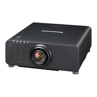
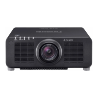
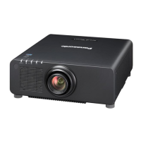
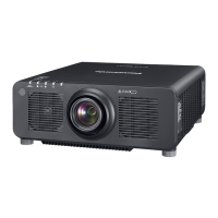
2. 3. Removal of A-P.C.Board Block
1. Remove top cover, front cover and side cover R following the procedure 2.2
2. 1) Remove 4 screws (ordinal + type: silver screw with washers) then remove the connector holding plate.
2) Remove 2 screws (ordinal + type: silver screw with washers) at the center/rear area of the body.
3. Remove 4 screws (ordinal + type silver screw) then remove the terminal cover from A-PCB block.
4. Remove 9 screws (3 x ordinal silver screws with washers, 1 ordinal silver screw, 1 ordinal black tap screw
and 4 hex box screws) then remove A-PCB block.
* Remove 2 screws (ordinal silver screws) then remove G-PCB.
connector
holding plate
A-PCB block
A-PCB block
Terminal cover
XTBT969FJK
XYN3+F6FJ
THEC084N
hexbox
XSB3+8FN
A-PCB block
XSB3+8FN
G-PCB
XYN3+F10FJ
XYN3+F6FJ
THEJ057J
XSB3+8FN
DIS-6
 Loading...

