1
1-11-2-1-18
7. REGARDING REFRIGERANT FILLING
(For refi lling due to a leak)
For fi lling and replacing all refrigerant
For refi lling refrigerant, fi rst collect all residual refrigerant and after vacuum dehydration using the vacuum pump. Refi ll the refrigerant according to the
prescribed amount stated on the placard affi xed to this unit.
Precautions after the pipes’ connection have completed
Ensure to open the 3-way valve after completing the piping installation, leak test and vacuuming. If it is closed during operation, it can lead to compressor failure.
Use tools that are designed specifi cally for R32, for pressure resistance and to prevent mixing impurities.
Fill the refrigerant from the 3-way valve’s service port on the liquid-side.
Precautions during refrigerant fi lling
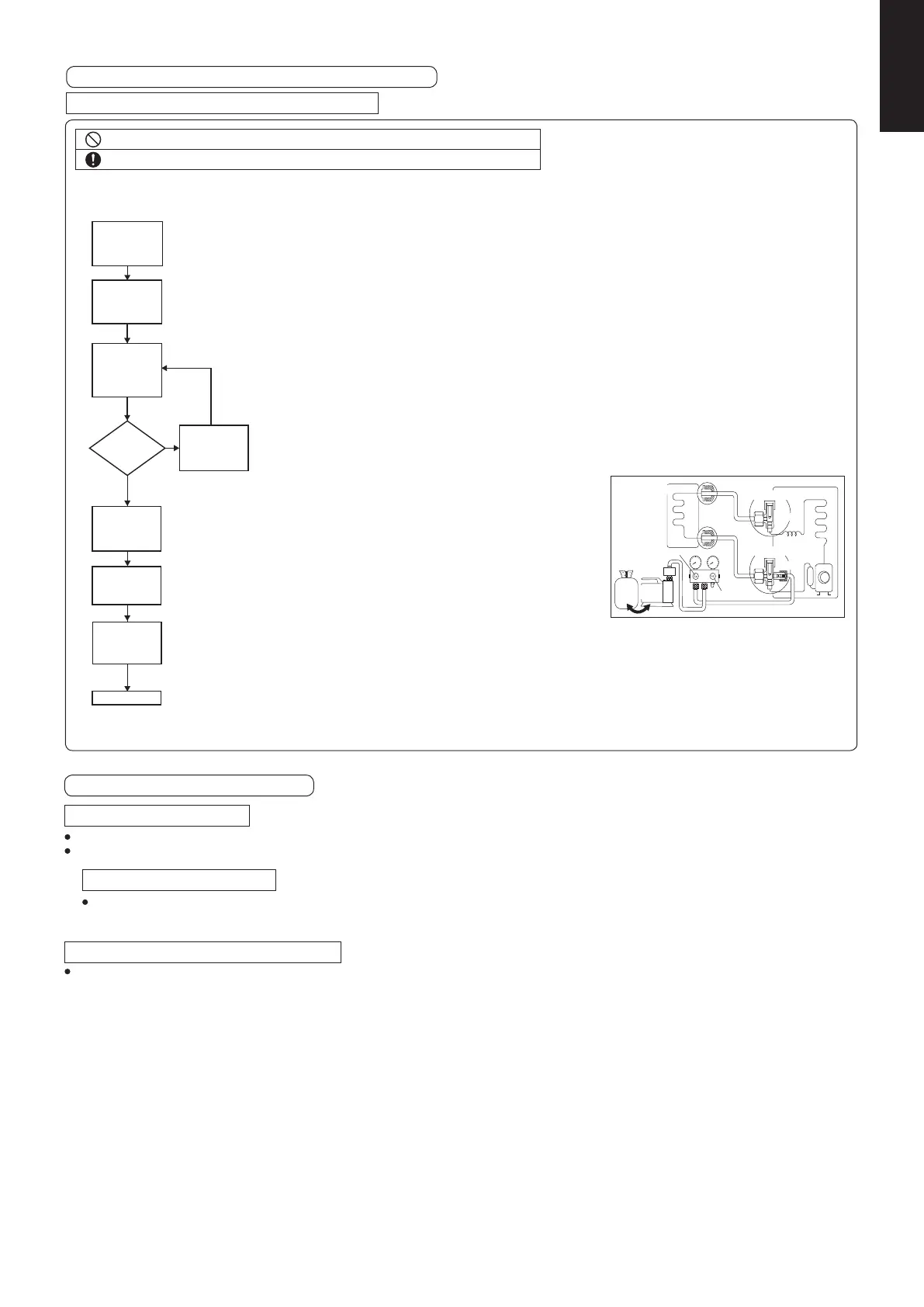
6. AIR TIGHTNESS TEST ON THE REFRIGERATING SYSTEM
AIR PURGING METHOD IS PROHIBITED FOR R32 SYSTEM
Liquid side
Tank
Cylinder
Indoor unit
Inert
gas
Vacuum
pump
OPEN
CLOSE
Gas side
Two-way valve
Close
Close
Three-way valve
Outdoor unit
Do not purge the air with refrigerants but use a vacuum pump to vacuum the installation.
There is no extra refrigerant in the outdoor unit for air purging.
•
•
Be sure to check whole system for gas leakage.
1) Connect a charging hose with a push pin to the Low side of a charging set and the service port of the 3-way valve.
2) Attach the gauge manifold set correctly and tightly. Make sure that both valves of the manifold gauge (low pressure and
high pressure) is in close position.
3) Connect the center hose of the manifold gauge to a vacuum pump.
4) Turn on the power switch of the vacuum pump, then turn open the low side manifold gauge valve and make sure that the
needle in the gauge moves from 0cmHg (0 MPa) to –76 cmHg (–0.1 MPa). This process continues for approximately
ten minutes. Then close the low side manifold gauge valve.
5) Remove the vacuum pump from the centre hose and connect the center hose to cylinder of any applicable inert gas as test gas.
6) Charge test gas into the system and wait until the pressure within the system to reach min. 1.04MPa (10.4barg).
7) Wait and monitor the pressure reading on the gauges. Check if there is any pressure drop. Waiting time depends on the
8) If there is any pressure drop, perform step 9-12. If there is no pressure drop, perform step 13.
9) Use Gas Leak Detector to check for leaks. Must use the detection equipment with a sensitivity of 5 grams per year of test
10) Move the probe along the air conditioning system to check for leaks, and mark for repair.
11) Any leak detected and marked shall be repaired.
12) After repair, repeat evacuation steps 3-4 and tightness test steps 5-7.
Check the pressure drop as in step 8.
13) If no leak,
Recover the test gas. Perform evacuation of steps 3-4.
Then proceed to step 14.
14) Disconnect the charging hose from the service port of the 3-way valve.
15) Tighten the service port caps of the 3-way valve at a torque of 18 N•m
with a torque wrench.
16) Remove the valve caps of both of the 2-way valve and 3-way valve.
17) Open both of the valves, using a hexagonal wrench (4mm).
18) Mount back the valve caps onto the 2-way valve and the 3-way valve to complete this process.
Notes:
Recommended use of any of the following leak detector,
I) Universal Sniffer leak detector
II) Electronic halogen leak detector
III) Ultrasonic Leak Detector
Preparation
(Step 1-2)
Evacuation
(Step 3-4)
Tightness Test
with Inert Gas
(Step 5-7)
Pressure drop?
(Step 8)
Leak detection
and repair
(Step 9-12)
Recovery of
Test Gas
(Step 13)
Yes
No
Evacuation
(Step 3-4)
Open
2 and 3 valves
(Step 14-18)
Complete
Before system is charged with refrigerant and before the refrigerating system is put into operation, below site test procedure and acceptance criteria shall
be vertifi ed by the certified technicians, and/or the installer.
size of the system.
gas or better.
Ensure not to scratch the inner surface of the valve or the end of the valve shaft.
• Once adjustments to the valve are completed, ensure to tighten the valve cap according to
• the prescribed torque.
Precautions for handling the valve cap
Caulking treatment, etc.
Insulation
material
Piping
Use a push-rod with a charge hose.
• Once adjustments to the valve are completed, ensure to tighten the valve cap according to
• the prescribed torque.
Precautions for handling the service ports
For proper connection, align the union and fl are straight with each other.
Ensure that the pipes do not come into contact with the compressor’s bolts or exterior panel.
There is a risk of condensation from the 3-way valve coming out between the insulation material and the indoor unit’s piping when you install the outdoor unit above then the
indoor unit. Ensure to caulk the connection parts.
Precautions for connecting the pipes
Use materials with good heat-resistant properties as the heat insulator for the pipes. Ensure to insulate both the gas side and liquid side pipes.
If the pipes are not adequately insulated, condensation and water leakages may occur.
Ensure that the current insulation covers the pipes up to the unit’s connecting part.
If the piping is exposed, it may cause condensation or burn (when touch the pipe).
Precautions for insulation installation Maximum temperature limit of gas or liquid piping is 120 °C
Precautions for flare nut installation
Dimensions when adding fl are nuts and the tightening torque
A snoisnemid noitces eralF).xorppa( euqrot gninethgiTezis gnipiP finoc eralF guration
ø 6.35 18.0 N•m (180
f•cm) 8.7 ~ 9.1 mm
90° ± 2°
45° ±1°
ø 9.52 42.0 N•m (420 f•cm) 12.8 ~ 13.2 mm
ø 12.7 55.0 N•m (550
f•cm) 16.2 ~ 16.6 mm
ø 15.88 65.0 N•m (650
f•cm) 19.3 ~ 19.7 mm
After piping connection has completed, ensure there is no gas leakage.
When tightening the fl are nut, coat the fl ares (inner surface only) with refrigerant oil on the fl ares
Firstly, screw in 3-4 turns by hand.
Ensure not to get oil on the screw part.
Refrigerant oil used is ether-based.
Once the piping connections are completed, perform leakage inspection using nitrogen gas.
When fl ared joints are reused, the fl are part shall be re-fabricated.
Application for ether-based oil
Tightening torque (approx.)
Valve cap
(Valve size)
ø6.35 (1/4")
14N•m~18N•m
(140
f•cm~180 f•cm)
ø12.7 (1/2")
49N•m~55N•m
(490
f•cm~550 f•cm)
ø15.88
48.0N•m~59.8N•m
(480
f•cm~598 f•cm)
Service port
10.7N•m~14.7N•m
(107
f•cm~147 f•cm)
[3-way valve operation method]
• Use an Allen wrench.
Direction to open
Opening : Open the cover and turn the
Allen wrench counter-clockwise
until it stops.
Closing : Open the cover and turn the
Allen wrench clockwise until it
stops.
Ensure to do the re-fl aring of pipes before connecting to units to avoid leaking.
To prevent the ingress of moisture into the joint which could have the potential to freeze and
then cause leakage, the joint must be sealed with suitable silicone and insulation material.
The joint should be sealed on both liquid and gas side.
Insulation material and silicone sealant. Please ensure
there are no gaps where moisture can enter the joint.
Silicone Sealant must be neutral cure and ammonia free. Use of
silicon containing ammonia can lead to stress corrosion on the
joint and cause leakage.
Observe the followings to decide reusing the existing refrigerant piping.
Poor refrigerant piping could result in product failure.
In the circumstances listed below, do not reuse any refrigerant piping. Instead, make sure to install a new piping.
Heat insulation is not provided for either liquid-side or gas-side piping or both.
The existing refrigerant pipe has been left in an open condition.
The diameter and thickness of the existing refrigerant piping does not meet the requirement. (Refer to above tables)
The piping length and elevation does not meet the requirement. (Refer to above tables)
Use only R32 or R410A genuine branch pipe.
Perform proper pump down for operated product before reuse piping.
In the circumstances listed below, clean it throughly before reuse.
Pump down operation cannot be performed for the existing air conditioner.
The compressor has a failure history.
Oil color is darken. (ASTM 4.0 and above)
The existing air conditioner is gas/oil heat pump type.
Do not reuse the fl are to prevent gas leak. Make sure to install a new fl are.
If there is a welded part on the existing refrigerant piping, conduct a gas leak check on the welded part.
Replace deteriorated heat insulating material with a new one. Heat insulating material is required for both liquid-side and ga
s-side piping.
INCASE OF REUSING EXISTING REFRIGERANT PIPING
In high humidity environment, reinforce the insulation material for the refrigerant piping. Failure to do so may result in condensation on the surface of the
insulation material.
SM830283-00_欧州向け R32シングル36-71形TD&SM.indb 18 20/01/30 10:26:05
 Loading...