22
2-3-1-3
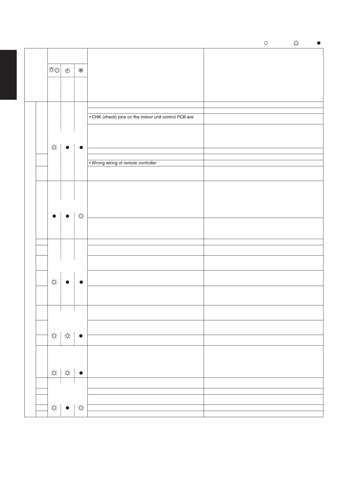
ON: Blinking: OFF:
Abnormal
Wireless remote
display
controller
Alarm contents
receiver display
Error location
Operation
Timer
Standby
Remote controller • Indoor Unit
E01
Operating lamp
blinking
• Replace the remote controller• Faulty remote controller
•
Disconnection / Contact failure of remote controller wiring
• Correct the remote controller wiring
short circuited
• Remove the short
• Execute auto address setting
E02
• Faulty setting of EEPROM (IC010) on indoor unit • Replace the indoor unit EEPROM
• Faulty remote controller • Replace the remote controller
E03
• Correct the remote controller wiring
• In the case of non-group control : Power supply OFF of
outdoor unit
Disconnection / Contact failure of inter-unit wiring
• In the case of group control : Auto address operation
was not carried out
• Error in indoor unit receiving signal from remote
controller (central)
E04
blinking
Standby lamp
• Check the indoor unit control PCB
• Check the remote controller wiring
• Check the inter-unit control wiring
• Disconnection / Contact failure of inter-unit wiring
• Faulty indoor unit control PCB
• Faulty outdoor unit control PCB
• Communication circuit fuse (F302) on indoor unit control
PCB opened
• Check the electrical connection of inter-unit control wiring
• Replace the indoor unit control PCB
• Replace the outdoor unit control PCB
• Check the electrical connection of fuse (F302) on indoor
unit control PCB
In the case of the fuse opened on an indoor unit control
PCB, after correcting wiring connection, it substitutes an
EMG plug for OC plug
E08
• Fuse on outdoor unit control PCB opened
Since failure of an outdoor fan motor is considered as a
cause, both outdoor unit control PCB and outdoor unit
fan motor are exchanged simultaneously
• In the case of the fuse opened on an outdoor unit control
PCB, replace both outdoor unit control PCB (CR/HIC) and
outdoor unit fan motor simultaneously
blinking
Operating lamp
• Duplication of indoor unit address setting • Indoor unit address re-setting
E09
E15
E16
E18
•
・Check the inter-unit control wiring
・Check the indoor and outdoor unit control PCB
・Address re-setting after correcting the combination of units
・Check the inter-unit control wiring
・Check the indoor and outdoor unit control PCB
・Address re-setting after correcting the combination of units
Correct the setting
• E
•
•
Auto Address Alarm
The total capacity of indoor units is too low
•
•
Auto Address Alarm
The total capacity of indoor units is too high
rror because of more than one remote controller setting
to main
F01
Operating
• Correct the wiring connection
• Replace the wiring
• Replace the indoor unit control PCB
and timer
• Disconnection of wiring between main unit and additional
units
• Contact failure of wiring
• Faulty indoor unit control PCB (main or addition)
lamp blinking
alternately
• Indoor heat exchanger temperature sensor (E1) trouble
F02
• Check the indoor unit heat exchanger temperature sensor
(E1)
• Check the indoor unit control PCB
• Indoor heat exchanger temperature sensor (E2) trouble
F10
• Check the indoor unit heat exchanger temperature sensor
(E2)
• Check the indoor unit control PCB
• Indoor air temperature sensor (TA) trouble
F29
Operating
• Check the indoor unit air temperature sensor (TA)
• Check the indoor unit control PCB
and timer
lamp blinking
simultaneously
• Indoor unit EEPROM trouble
L02
• Check the indoor unit EEPROM
• Check the indoor unit control PCB
Operating
and standby
lamps blinking
simultaneously
• Setting error, indoor / outdoor unit type / model miss-
matched
L03
L07
• Duplication of main indoor unit address in group control • Correct the group (main and addition)
L08
• Correct the indoor unit address
• Address re-setting after correcting the combination of units
• Indoor unit address is not set
• Group control wiring is connected to individual control
indoor unit
L09
• Correct the indoor unit address
• Indoor unit capacity is not set • Correct the capacity setting of indoor units
2-3-1-5. Contents of Remote Controller Switch Alarm Display
U-36PZ3E5, U-50PZ3E5, U-60PZ3E5, U-71PZ3E5
Remote controller • Indoor Unit
ON: Blinking: OFF:
Abnormal
Wireless remote
display
controller
Alarm contents
receiver display
Error location
Operation
Timer
Standby
P01
and Timer
standby
lamp blinking
alternately
P09
• Indoor unit fan motor locked
• Indoor unit fan motor layer short
• Contact failure in thermostat protector circuit
P10
• Remove the cause
• Replace the fan motor
• Correct the wiring
• Faulty wiring connections of (ceiling) indoor unit panel • Correct the wiring connection
• Correct insertion direction of connector (Hook is outside)
P11
• Faulty drain pump
• Drainage failure
• Repair / Replace
• Correct
• Correct the wiring
P12
P31
• Faulty drain pump
• Drain pump locked
• Repair / Replace
• Remove the cause
• Indoor unit fan motor locked
• Faulty wiring connections of indoor unit fan motor
• Rem
• Indoor unit in group control trouble • Repair indoor unit which blinking alarm
ove the cause
• Correct the wiring
SM830283-00_欧州向け R32シングル36-71形TD&SM.indb 3 2020/01/29 19:52:16
 Loading...