88
Control of 2WAY SYSTEM
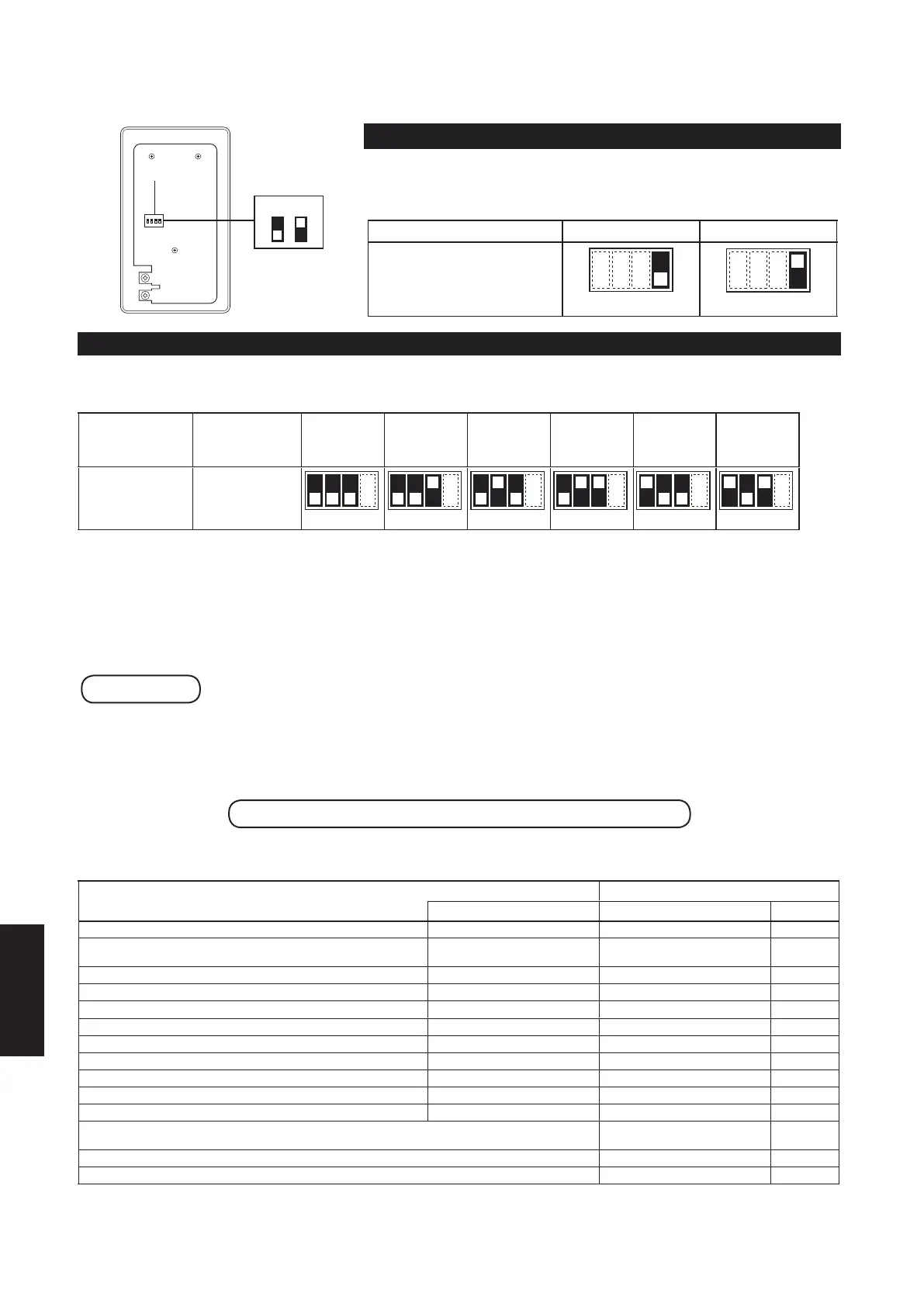
2. Wireless Remote Controller
4. Setting Address Switches
5. Test operation
Main/Sub setting Address setting
Remove the top case of the receiver for setting.
Main/Sub setting
1 2 3 4
Switch
ONOFF
Use this to set Main/Sub for the remote controller and the receiver.
Set one to [Main] and the other to [Sub].
Factory default: [Main]
It is recommended to set the wired remote controller to [Main].
BUSNIAMbuS/niaM
Main/Sub switch position
123 4
123 4
Address setting
When more than 1 receiver is installed in the same room, setting addresses prevents interference.
For how to change addresses of wireless (infrared) remote controllers, see “Matching Up Addresses” of wireless (infrared) remote controllers
on page 8-9.
Wireless (infrared)
remote controller
address display
Address Address Address Address Address Address Address
ALL 12345 6
Address
switch position
Receiving is
possible at all
address positions.
123 4 123 4 123 4 123 4 123 4 123 4
Preparation :
Turn on the circuit breaker of units and then turn the power on. After the power is turned on, remote controller operation is ignored
for approx. 1 minute because setting is being made. This is not malfunction. (Contents received while setting are disabled.)
1. To start test operation, press and hold the emergency operation button for 10 seconds.
2. The indication lamps (OPERATION, TIMER, STANDBY) blink during test operation.
.sdnoces 01 rof nottub noitarepo ycnegreme eht dloh dna sserp ,noitarepo tset hsin if oT .3
Attention
Do not use this mode for purposes other than the test operation.
(To prevent overload of the units)
Read the installation instructions supplied with the units.
Any of the Heat, Cool and Fan operations can only be performed.
Temperature cannot be changed.
The test operation mode is automatically turned off in 60 minutes.
(To prevent continuous test operation)
Outdoor units do not operate for approx. 3 minutes after the power is
turned on or operation is stopped.
Self-diagnostics table and detected contents
The “Alarm Display” shown in the table below expresses the alarm contents displayed when the wired remote controller is connected. For how
to handle the alarms, see Section 2 “2-5. Contents of Remote Controller Switch Alarm Display” and Section 5 “5-1. Contents of Remote
Controller Switch Alarm Display”.
reviecerehtnopmalnoitacidnIstnetnocdetceteD
Alarm Display
OPERATION TIMER STANDBY
Blinking
E01–E03, E08–E14, E17, E18
Communication error either in the in/outdoor operation line or
the sub-bus of the outdoor unit
E04–E07, E15, E16, E19–E31
Operation of indoor protection device
P01, P09–P14
Alternately
13P–51P,80P–20PecivednoitcetorproodtuofonoitarepO
Alternately
11F–01F,30F–10FrotsimrehtroodniehtnirorrE
Alternately
82F–21F,90F–40FrotsimrehtroodtuoehtnirorrE
Alternately
92FMORPEEroodniehtnirorrE
Simultaneously
13F,03FMORPEEroodtuoehtnirorrE
Simultaneously
13H–10HrosserpmocehtotdetalerrorrE
90L–50L,30L–10LsgnittesroodninirorrE
Simultaneously
13L–01L,40LsgnittesroodtuonirorrE
Simultaneously
Inconsistency in Air/Heat (Including an auto-temp setting
for a model without auto-temp settings)
Alternately
Oil Alarm (Same as operation of outdoor protection device)
Alternately
Test operation
Simultaneously
: OFF : ON (Illuminated) : Blinking (0.5 seconds interval)
Communication error in the remote controller circuit
8-3-9
SM830283-00_欧州向け R32シングル36-71形TD&SM.indb 9 20/01/14 10:04:22
 Loading...