1
1-11-1-1-2
■
HOW TO INSTALL THE INDOOR UNIT
3. HOW TO INSTALL THE INDOOR UNIT
●
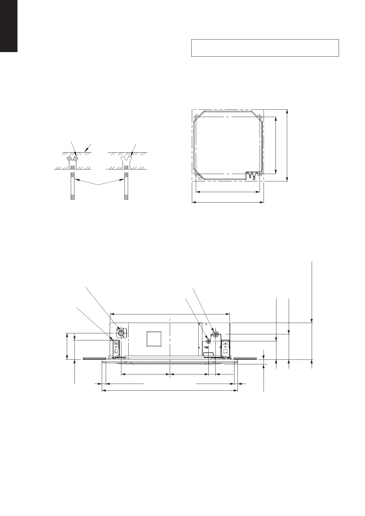
Preparation for Suspending
This unit uses a drain pump. Use a carpenter’s level to check
that the unit is level.
●
Suspending the Indoor Unit
(1) Fix the suspension bolts securely in the ceiling using
the method shown in the diagrams, by attaching them
to the ceiling support structure, or by any other method
that ensures that the unit will be securely and safely
suspended.
Note: For DC Fan Tap Change Procedure for 4-Way
Cassette, see page 1-11-1-1-14.
Hole-in-anchor
Hole-in-plug
Concrete
Insert
Suspension bolt
(M10 or 3/8")
(field supply)
Drain outlet (other side)
(VP25)
Suspension lug
* Over 20 mm
* Over 20 mm
340 mm
840 mm
950 mm
272 mm
50 mm
Refrigerant tubing joint (liquid side)
Refrigerant tubing joint (gas side)
184 mm
134 mm
33.5 mm
177 mm
127 mm
Indoor Unit
View from top
A: 700 mm
A: 780 mm
B: 860 ~ 910 mm
A: (suspension bolt pitch)
B: (ceiling opening dimension)
B: 860 ~ 910 mm
(2) Follow the diagram to make the holes in the ceiling.
(3) Determine the pitch of the suspension bolts using the supplied full-scale installation diagram (printed on container box).
The diagram show the relationship between the positions of the suspension fitting, unit, and panel.
Use the nut (field supply) and washer (supplied) for upper and lower position of the suspension lug.
* The overlapping portion between the ceiling and panel for cassette should be kept over 20 mm.
281258_EU.indb 8 2016-9-1 13:03:40
S-3650PU3E: 256 mm
S-6071PU3E: 256 mm
SM830283-00_欧州向け R32シングル36-71形TD&SM.indb 2 20/01/30 10:25:03
 Loading...