1
1-11-1-1-14
Others
Setting No.
(1)
Remote controller
setting data
Item code 5d
0001
Contents &
optional parts name
Air-flow blocking kit
(for 3-way air flow)*
2
1
High-ceiling setting 1*
2
(3) 0003
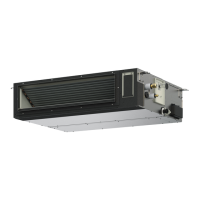
Air-flow blocking kit
(when a duct is
connected.)
(6)
High-ceiling setting 2*
2
0006
(1) Checking After Installation
1) Check that there are no gaps between the unit and the
panel for cassette, or between the panel for cassette
and the ceiling surface.
* Gaps may cause water leakage and condensation.
2) Check that the wiring is securely connected.
* If it is not securely connected, the auto flap will not
operate.
(“P09” is displayed on the remote controller.)
In addition, the water leakage and condensation may
occur.
(2) Operating the Wireless Remote Controller
For details of installation, refer to the section “Wireless
Signal Receiver” in the supplied installation instructions.
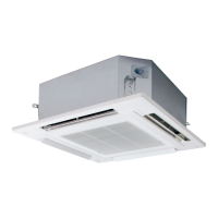
(3) Selecting DC Fan Motor Tap (4-Way Cassette)
Check the optional parts accordingly in the following
table.
Table for DC Fan Motor Tap Settings*
Air-flow blocking kit
(for 2-way air flow)*
2
*1 When using optional parts in different setting No. in
*2 Ceiling height (m)
combination with multiple units, conform it to the larger
setting No.
Indoor unit type
S-3650PU3E S-6071PU3E
Standard
2.7
3.0
(factory setting)
High-ceiling setting 1
3.2
3.3
High-ceiling setting 2
3.5
3.6
3.8
3.8
Air-flow blocking kit
(for 3-way air flow)
4.2
4.2
Air-flow blocking kit
(for 2-way air flow)
1) When setting on the indoor unit control PCB
<Procedure>
Stop the system before performing these steps.
1
Open the electrical component box cover, then
check the indoor unit control PCB.
2
Change the DIP switch (SW001) on the indoor unit
control PCB in accordance with the setting number
which was confirmed in “Table for DC Fan Motor
Tap Settings”.
Setting No. DIP switch Setting No. DIP switch
(1)
TP6
TP3
TP1
ON
1 2 3
(6)
ON
TP6
1 2 3
TP3
TP1
(3)
ON
TP6
1 2 3
TP3
TP1
<Procedure of CZ-RTC5B>
Stop the system before performing these steps.
1
Keep pressing the
, and buttons
simultaneously for 4 or more seconds.
The “Maintenance func” screen appears on the LCD
display.
2
Press the or button to see each menu.
press the
button.
If you wish to see the next screen instantly, press the
or button.
Select “8. Detailed settings” on the LCD display and
The “Detailed settings” screen appears on the LCD display.
TP6
TP3
TP1
1
ON
2 3
TP6
TP3
TP1
1 2 3
SW001
Indoor unit control PCB
Setting example
1: OFF
2: OFF
ON
3: ON
Maintenance func
Sel.
20:30 (THU)
Page [ ] Confirm
1. Outdoor unit error data
2. Service contact
3. RC setting mode
4. Test run
Maintenance func
Sel.
20:30 (THU)
Page [ ] Confirm
5. Sensor info.
6. Servicing check
7. Simple settings
8. Detailed settings
SM830283-00_欧州向け R32シングル36-71形TD&SM.indb 14 20/01/30 10:25:11
 Loading...