EasyManua.ls Logo

Panasonic SA-PM91DEE

Panasonic SA-PM91DEE
148 pages
To Next Page IconTo Next Page
Loading...
n Amplifier Section
RMS Output Power Stereo mode (Both channel driven)
10% total harmonic distortion
1 kHz, (Low channel) 40 W per channel (6)
8 kHz, (High channel) 40 W per channel (6)
Total RMS Stereo mode power 160 W
DIN Output Power Stereo mode (Both channel driven)
10% total harmonic distortion
1 kHz, (Low channel) 35 W per channel (6)
8 kHz, (High channel) 35 W per channel (6)
Total RMS Stereo mode power 140 W per channel
Phone jack terminal Stereo, 3.5 mm jack
n Disc Section
Disc played [8cm or 12 cm]
1. DVD-RAM (DVD-VR compatible, JPEG formatted disc)
2. DVD-Audio
3. DVD-Video
4. DVD-R (DVD-Video compatible)
5. DVD-RW, +R, +RW
6. CD-Audio (CD-DA)
7. Video CD
8. SVCD (Conforming to IEC62107)
9. CD-R/CD-RW
(CD-DA, Video-CD, SVCD, MP3, WMA, JPEG formatted discs)
© 2005 Matsushita Electric Industrial Co. Ltd.. All
rights reserved. Unauthorized copying and
distribution is a violation of law.
SA-PM91DEE
Colour
(S) ... Silver Type
10. MP3/WMA*
·
Compatible compression rates:
MP3: between 32 kbps and 320 kbps
WMA: between 48 kbps and 320 kbps
11. JPEG*
·
Exif Ver 2.1 JPEG Baseline files
·
Picture resolution:
between 320 x 240 and 6144 x 4096 pixels
(Sub sampling is 4:2:2 or 4:2:0)
12. HighMAT Level 2 (Audio and Image)
13. HDCD
* The total combined maximum number of recognizable audio and
picture contents and groups: 4000 audio and picture contents and
400 groups.
A
udio output
Number of channels 2
Digital audio output
Optical digital output Optical terminal
Pick up
Wavelength
DVD 662 nm
CD 785 nm
Laser power CLASS 2/CLASS 3a
n Video Section
Video system PAL625/50, PAL525/60, NTSC
DVD Stereo System
Specification
ORDER NO. MD0504152C3

Table of Contents

Question and Answer IconNeed help?

Do you have a question about the Panasonic SA-PM91DEE and is the answer not in the manual?

Panasonic SA-PM91DEE Specifications

General IconGeneral
BrandPanasonic
ModelSA-PM91DEE
CategoryDVD Player
LanguageEnglish

Summary

Specification

Amplifier Section

Details amplifier output power, distortion, and terminals.

Disc Section

Lists supported disc formats and types.

Safety Precautions

GENERAL GUIDELINES

General guidelines for servicing and safety checks.

LEAKAGE CURRENT COLD CHECK

Procedure for performing a cold check of leakage current.

LEAKAGE CURRENT HOT CHECK

Procedure for performing a hot check of leakage current.

Before Repair and Adjustment

Protection Circuitry

Explains operation and troubleshooting of protection circuitry.

Prevention of Electro Static Discharge (ESD) to Electrostatically Sensitive (ES) Devices

ESD Precautions and Techniques

Techniques to reduce component damage from static discharge.

Precaution of Laser Diode

CAUTION: Unit utilizes Class 1 laser.

Safety precautions when operating near the laser pickup.

Cautions to be taken when handling Optical Pickup

Handling Optical Pickup

Instructions for safely handling the optical pickup unit.

Grounding for Preventing Electrostatic Destruction

Methods for grounding to prevent electrostatic damage.

Accessories

Operation Procedures

Main unit Controls

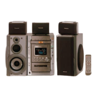
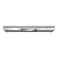
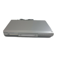
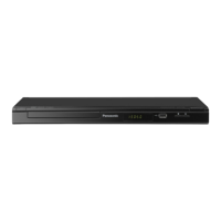
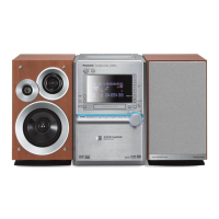
Describes the controls and functions of the main unit.

Remote Control Functions

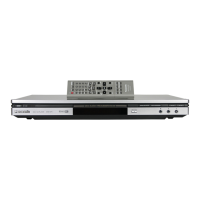
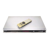
Details the buttons and functions of the remote control.

Disc Information

Discs that can be played

Lists the types of discs supported by the player.

HighMAT Technology

Information on HighMAT, MPEG Layer-3, and licensing.

About HighMAT

Whats HighMAT?

Explanation of HighMAT technology and its purpose.

Why take advantage of HighMAT?

Benefits of using HighMAT for digital media organization.

Benefits of HighMAT?

Assembling and Disassembling.

ATTENTION SERVICER

General warnings for servicers regarding chassis edges.

Index of Disassembly Procedures

Lists disassembly steps for various unit components.

Disassembly flow chart

Disassembly of DVD Mechanism Unit

Checking Procedure for Each Major P.C.B.

Replacement of the Power Amplifier IC

Procedure for replacing the power amplifier IC.

Self-Diagnosis Function

Automatic Displayed Error Codes

Explains automatically displayed error codes and their meaning.

Memorized Error Codes

How to activate and display memorized error codes.

DVDCD Self-Diagnosis Error Code Description

Cautions To Be Taken During Servicing

DVD Player Firmware Version Upgrade Process

Process for upgrading DVD player firmware.

Using Recovery Disc

Recovery Process

Steps to perform the recovery process with a disc.

Procedure for Checking Operation of Individual Parts for Deck Mechanism Unit

Operation Check with Cassette Tape

Procedure for checking deck mechanism operation with tape.

Measurement And Adjustments

Cassette Deck Section

Lists necessary equipment and tapes for cassette deck measurement.

Tape Speed Adjustment

Procedure for adjusting tape speed.

Voltage Measurement and Waveform Chart

Voltage Measurement

Voltage measurement data for the DVD module PCB.

Waveform

Block Diagram

DVD Module Block

Block diagram of the DVD module.

Main Block

Notes of Schematic Diagram

Importance safety notice

Safety notices regarding component replacement.

Schematic Diagram

Optical Pickup Unit Circuit

Schematic diagram of the optical pickup unit circuit.

DVD Module Circuit

Schematic diagram of the DVD module circuit.

Main Circuit

Schematic diagram of the main circuit.

Panel Circuit, Harmonic Bass Circuit & Switch Circuit

Schematic diagrams for panel, harmonic bass, and switch circuits.

Scart Terminal Circuit & Speaker Circuit

Schematic diagrams for scart terminal and speaker circuits.

Power Circuit

Schematic diagram of the power circuit.

Deck Circuit, Tape Eject Circuit & Deck Mechanism Circuit

Schematic diagrams for deck, tape eject, and mechanism circuits.

CD Loading Circuit

Schematic diagram of the CD loading circuit.

Printed Circuit Board

DVD Module P.C.B. (Side: A & B)

Component layout diagram for the DVD module PCB.

Main P.C.B.

Transformer P.C.B.

Power P.C.B.

Deck P.C.B. & Tape Eject P.C.B.

Deck Mechanism P.C.B. & CD Loading P.C.B.

Scart Terminal P.C.B. & Harmonic Bass P.C.B.

Switch P.C.B. & Speaker P.C.B.

Wiring Connection Diagram

Type Illustrations of ICs, Transistors & Diodes

Terminal Function of ICs

IC2801(C2 CBJG000573) Microprocessor

Terminal functions and I/O for the microprocessor IC.

Parts Location and Replacement Parts List

Notes:

Safety notes, warnings, and general information for parts lists.

Deck Mechanism (RAA4110-S)

Deck Mechanism Parts Location

Exploded view showing the location of deck mechanism parts.

CD Loading Mechanism

CD Loading Mechanism Parts Location

Exploded view showing CD loading mechanism parts.

Cabinet

Cabinet Parts Location

Exploded view of cabinet parts and their locations.

Electrical Parts List

INTEGRATED CIRCUITS

List of integrated circuits used in the unit.

TRANSISTORS

List of transistors used in the unit.

DIODES

List of diodes used in the unit.

CHIP INDUCTORS

List of chip inductors.

RESISTORS

List of resistors.

SWITCHES

List of switches.

CONNECTORS

List of connectors.

Packing Materials & Accessories Parts List

Packaging

Diagram showing the packaging of the product.

Related product manuals