Composite video output
Output level 1Vp-p(75Ω)
Terminal Pinjack(1system)
S-Video output
Y output level 1Vp-p(75Ω)
C output level 0.3 Vp-p (75Ω)(PAL)
0.286 Vp-p (75Ω)(NTSC)
Terminal S terminal (1 system)
RGB video output
R output level 0.7 Vp-p (75Ω)
G output level 0.7 Vp-p (75Ω)
B output level 0.7 Vp-p (75Ω)
Terminal SCART jack
n Cassette Deck Section
Track system 4-track, 2-channel
Heads
Record/playback Solid permalloy head
Erasure Double gap ferrite head
Motor DC servo motor
Recording system AC bias 100 kHz
AC erase 100 kHz
Tape speed 4.8 cm/sec
Overall frequency response (+3, -6 dB) at Deck Out
Normal 35 Hz - 14 kHz
S/N ratio 50 dB (A weighted)
Wow and flutter 0.18% (WRMS)
Fast forward and rewind time Approx. 120 seconds with C-60
cassette tape
n FM Tuner Section
1 Safety Precautions 4
1.1. GENERAL GUIDELINES
4
2 Before Repair and Adjustment
5
3 Protection Circuitry
5
4 Prevention of Electro Static Discharge (ESD) to
Electrostatically Sensitive (ES) Devices
5
5 Handling the Lead-free Solder
6
5.1. About lead free solder (PbF)
6
6 Precaution of Laser Diode
7
7 Cautions to be taken when handling Optical Pickup
8
7.1. Handling Optical Pickup
8
7.2. Replacing Precautions for Optical Pickup Unit
8
7.3. Grounding for Preventing Electrostatic Destruction
8
Frequency range 87.50 - 108.00 MHz
(50 kHz step)
Sensitivity 1.6 µV (IHF)
S/N 26 dB 1.5 µV
ntenna terminals 75 Ω (unbalance)
Preset stations 15
n AM Tuner Section
Frequency range 522 - 1629 kHz (9 kHz steps)
Sensitivity
S/N 20 dB at 999 kHz 560 µV/m
Image rejection at 999 kHz 40 dB
Preset stations 15
n General
Power supply AC 230 V, 50 Hz
Power consumption 140 W
Dimensions (W x H x D) 175 mm x 248 mm x 388 mm
Mass 5.8 kg
Operating temperature range +5°C to + 35°C
Operating humidity range 5% to 90% RH (no
condensation)
Power consumption in standby mode 0.5 W
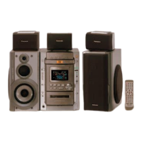
n System
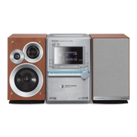
n System: SC-PM91DEE-S
Music Center: SA-PM91DEE-S
Speaker: SB-PM91P-MJ
Notes :
1. Specifications are subject to change without notice.
Mass and dimensions are approximate.
2. Total harmonic distortion is measured by the digital spectrum
analyzer.
8 Accessories
9
9 Operation Procedures
10
10 Disc Information
12
11 About HighMAT
14
11.1. What 痴 HighMAT?
14
11.2. Why take advantage of HighMAT?
14
11.3. Benefits of HighMAT?
15
12 Assembling and Disassembling.
18
12.1. Disassembly flow chart
19
12.2. Disassembly of Side Panel (L) & (R)
20
12.3. Disassembly of Top Cabinet Unit
20
12.4. Disassembly of Deck Mechanism and Tape Eject P.C.B
20
12.5. Disassembly of Front Panel Assembly
21
CONTENTS
Page Page
2
SA-PM91DEE