EasyManua.ls Logo

Panasonic SA-PT760P - User Manual

Panasonic SA-PT760P
154 pages
Print Icon
To Next Page IconTo Next Page
Loading...
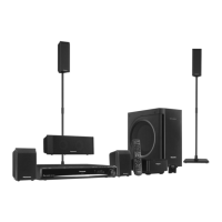
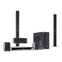
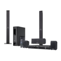
Main unit SA-PT760P/PC
O
OO
OGENERAL
Power supply: AC 120 V, 60 Hz
Power consumption: This unit 130 W
Power consumption in standby mode:
approx. 0.3 W
Dimensions (W×H×D): 430 mm×63 mm×327 mm(16-
15/16” X 2-11/16” X 12-7/8”)
Mass: This unit 3.7 kg
Operating temperature range: +0 °C to +40 °C
(+32 °F to +95 °F)
Operating humidity range: 35 % to 80 % RH
(no condensation)
O
OO
OAMPLIFIER SECTION
RMS Output Power: Dolby Digital Mode
Front Ch:
125 W per channel (3 ), 1 kHz, 10% THD
Surround Ch:
125 W per channel (3 ), 1 kHz, 10% THD
Center Ch:
250 W per channel (6 ), 1 kHz, 10% THD
Subwoofer Ch:
© 2008 Matsushita Electric Industrial Co. Ltd.. All
rights reserved. Unauthorized copying and
distribution is a violation of law.
SA-PT760P
SA-PT760PC
Colour
(K).......................Black Type
250 W per channel (6 ), 100 Hz, 10 % THD
Total RMS Dolby Digital mode power:
1000 W
FTC Output Power: Dolby Digital Mode
Front Ch:
63 W per channel (3 ), 120Hz to 20 kHz, 1% THD
Surround Ch:
34 W per channel (3 ), 120Hz to 20 kHz, 1% THD
Center Ch:
113 W per channel (6 ), 120Hz to 20 kHz, 1% THD
Subwoofer Ch:
121 W per channel (6 ), 45 Hz to120 Hz, 1 % THD
Total FTC Dolby Digital mode power:
428 W
O
OO
OFM TUNER, TERMINALS SECTION
Preset Memory: FM 30 stations
AM 30 stations
Frequency Modulation (FM)
Frequency range:
87.90-107.90 MHz (200-kHz step)
87.50-108.00 MHz (100-kHz step)
DVD Home Theater Sound System
Specifications
ORDER NO. MD0801014CE
A6

Table of Contents

Questions and Answers

Summary

Specifications

GENERAL

General operating specifications including power, dimensions, and environmental conditions.

AMPLIFIER SECTION

Details on the amplifier's output power for different channels in Dolby Digital mode.

FM TUNER, TERMINALS SECTION

Specifications for the FM tuner, including preset memory and frequency range.

1 Safety Precautions

1.1. GENERAL GUIDELINES

General guidelines for servicing, emphasizing safety and proper installation of protective devices.

1.2. Before Repair and Adjustment

Procedures to follow before performing repairs or adjustments, including capacitor discharge.

1.3. Protection Circuitry

Explanation of the protection circuitry and conditions that may activate it.

1.4. Safety Parts Information

Information on special safety parts critical for preventing hazards like shock or fire.

2 Prevention of Electrostatic Discharge (ESD) to Electrostatically Sensitive (ES) Devices

3 Precaution of Laser Diode

4 About Lead Free Solder (PbF)

4.1. Service caution based on legal restrictions

Cautions for repair work using lead-free solder, including melting point and soldering iron requirements.

5 Handling Precautions for Traverse Unit

5.1. Cautions to Be Taken in Handling the Optical Pickup Unit

Special care instructions for handling the optical pickup unit to prevent ESD damage.

5.2. Grounding for electrostatic breakdown prevention

Methods for grounding to prevent electrostatic discharge damage to sensitive devices.

6 Accessories

7 Operation Procedures

7.1. Remote Control Key Buttons Operations

Description of each button function on the remote control for unit operation.

7.2. Main Unit Key Buttons Operations

Description of each button function on the main unit for operation.

7.3. Using the VIERA Link “HDAVI Control”

Guide to operating the unit and TV linked via HDMI using VIERA Link HDAVI Control.

7.4. Using the iPod

Instructions on connecting and operating an iPod with the unit, including music and photo playback.

7.5. Audio and Video Connection

Procedures for connecting audio and video sources like TV, DVD, and component video.

7.6. Disc Information

Information on compatible disc types and file format support for playback.

8 Self-Diagnosis and Special Mode Setting

8.1. Service Mode Summary Table

Summary table for activating various service modes for checking the unit's functions.

8.2. Service Mode Table (For DVD)

Detailed table for DVD service modes, including error code checks and laser drive adjustments.

8.2.5. Optical Pick-up Self-Diagnosis

Procedure for optical pickup self-diagnosis and tilt adjustment for effective troubleshooting.

8.3. Service Mode Table (For CR14)

Service mode table specific to the CR14 mechanism, covering disassembly and reliability tests.

8.4. Wireless Service Mode Summary Table

Summary of service modes for checking wireless functions, including ID setting and RF channel display.

8.5. Service Mode Table (Wireless)

Detailed table for wireless service modes, covering transmitter type display and ID setting.

8.6. DVD Self Diagnostic Function-Error Code

Table listing DVD mechanism and module error codes, their descriptions, and FL display.

8.7. Sales Demonstration Lock Function

Procedure for activating and cancelling the sales demonstration lock function to prevent disc removal.

8.8. Service Precautions

Precautions to take after DVD player repair, including recovery processing and firmware updates.

9 Assembling and Disassembling

9.1. Disassembly Flow Chart

Flow chart illustrating the sequence for disassembling major components and PCBs.

9.2. Main Components and P.C.B. Locations

Diagram showing the locations of main components and printed circuit boards within the unit.

9.3. Disassembly of Top Cabinet

Step-by-step instructions for removing the top cabinet of the unit.

9.4. Disassembly of Rear Panel

Instructions for removing the rear panel, including screw removal and tab release.

9.5. Disassembly of DVD Mechanism Unit

Procedure for disassembling the DVD mechanism unit.

9.6. Disassembly of Front Panel

Step-by-step instructions for removing the front panel, including cable detachment.

9.7. Disassembly of Panel P.C.B.

Instructions for disassembling the panel PCB, including volume knob and shield plate removal.

9.8. Disassembly of Power;Disc Button P.C.B.

Procedure for disassembling the power/disc button PCB and associated panel angle.

9.9. Disassembly of DVD Lid

Instructions for disassembling the DVD lid, including lid holder and door spring removal.

9.10. Disassembly of Ipod Cradle P.C.B.

Step-by-step instructions for disassembling the iPod cradle PCB and its cover.

9.11. Disassembly of AC Inlet P.C.B.

Procedure for disassembling the AC inlet PCB, including shield plate and bracket removal.

9.12. Disassembly of Main P.C.B.

Instructions for disassembling the main PCB, including screw and cable removal.

9.13. Disassembly of D-Amp P.C.B.

Procedure for disassembling the D-Amp PCB, including screw and cable detachment.

9.14. Replacement of Digital Amp IC (IC5000)

Detailed steps for replacing the Digital Amp IC (IC5000) on the D-Amp PCB.

9.15. Replacement of Digital Amp IC (IC5200)

Detailed steps for replacing the Digital Amp IC (IC5200) on the D-Amp PCB.

9.16. Replacement of Digital Amp IC (IC5300)

Detailed steps for replacing the Digital Amp IC (IC5300) on the D-Amp PCB.

9.17. Disassembly of SMPS P.C.B.

Instructions for disassembling the SMPS PCB, including screw and cable removal.

9.18. Replacement of Switch Regulator IC (IC5701)

Steps for replacing the Switch Regulator IC (IC5701) on the SMPS PCB.

9.19. Replacement of Switch Regulator Diode (D5702)

Procedure for replacing the Switch Regulator Diode (D5702) on the SMPS PCB.

9.20. Replacement of Regulator Diode (D5801)

Steps for replacing the Regulator Diode (D5801) on the SMPS PCB.

9.21. Replacement of Regulator Diode (D5802)

Procedure for replacing the Regulator Diode (D5802) on the SMPS PCB.

9.22. Replacement of Regulator Diode (D5803)

Steps for replacing the Regulator Diode (D5803) on the SMPS PCB.

9.23. Disassembly of Power Supply P.C.B.

Instructions for disassembling the Power Supply PCB, including cable and screw removal.

9.24. Replacement of Regulator IC (IC2903)

Steps for replacing the Regulator IC (IC2903) on the Power Supply PCB.

9.25. Disassembly of DVD Module P.C.B.

Procedure for disassembling the DVD Module PCB, including cable and shield plate removal.

9.26. Disassembly of Coprocessor P.C.B.

Instructions for disassembling the Coprocessor PCB, including cable and connector removal.

9.27. Disassembly of Wireless Adapter P.C.B.

Procedure for disassembling the Wireless Adapter PCB, including screw and cable removal.

10 Assembling and Disassembling of DVD Mechanism Unit

10.1. Disassembly of TRV unit

Step-by-step instructions for disassembling the TRV unit from the DVD mechanism.

10.2. Assembly of TRV unit

Instructions for assembling the TRV unit back into the DVD mechanism.

11 Service Fixture and Tools

12 Service Position

12.1. Checking & Repairing Main P.C.B.

Procedure for checking and repairing the main PCB, including connection details.

12.2. Checking & Repairing D-Amp P.C.B.

Steps for checking and repairing the D-Amp PCB, including cable connections.

12.3. Checking & Repairing SMPS P.C.B.

Procedure for checking and repairing the SMPS PCB, including cable and screw removal.

12.4. Checking & Repairing Power Supply P.C.B.

Steps for checking and repairing the Power Supply PCB, including component removal.

12.5. Checking & Repairing DVD Module P.C.B.

Procedure for checking and repairing the DVD Module PCB, including top cabinet and rear panel removal.

13 Measurements and Adjustments

13.1. Service Tools and Equipment

List of service tools and equipment required for measurements and adjustments.

13.2. Important points in adjustment

Key considerations for optical and electrical adjustments, including anti-static measures.

13.3. Storing and handling of test discs

Guidelines for proper storage and handling of test discs to ensure accuracy.

13.4. Optical adjustment

Detailed procedure for optical pickup tilt adjustment to minimize jitter.

14 Voltage and Waveform Chart

14.1. DVD Module P.C.B.

Table of voltage measurements for various points on the DVD Module P.C.B.

14.2. D-Amp P.C.B.

Table of voltage measurements for various points on the D-Amp P.C.B.

14.3. Main P.C.B.

Table of voltage measurements for various points on the Main P.C.B.

14.4. Panel P.C.B.

Table of voltage measurements for various points on the Panel P.C.B.

14.5. Power Supply P.C.B.

Table of voltage measurements for various points on the Power Supply P.C.B.

14.6. SMPS P.C.B.

Table of voltage measurements for various points on the SMPS P.C.B.

14.7. Waveform Chart

Illustrations and descriptions of various waveforms for troubleshooting and testing.

15 Illustration of IC’s, Transistors and Diodes

16 Wiring Connection Diagram

17 Block Diagram

17.1. System Control

Block diagram illustrating the system control flow and interconnections.

17.2. DVD (Servo)

Block diagram showing the DVD servo system circuit and its signal lines.

17.3. DVD (Audio)

Block diagram illustrating the DVD audio signal processing and output circuitry.

17.4. DVD (HDMI)

Block diagram for the DVD HDMI output interface, including transmitter and signal paths.

17.5. VIDEO

Block diagram showing the video signal processing path for composite and component outputs.

17.6. Audio

Block diagram illustrating the audio signal processing, mixing, and output stages.

17.7. Digital Audio Amp

Block diagram of the digital audio amplifier section, showing ICs and signal flow.

17.8. Power

Block diagram of the power supply system, illustrating voltage regulation and distribution.

18 Schematic Diagram Notes

19 Schematic Diagram

19.1. DVD Module Circuit

Detailed schematic of the DVD Module (DV5) circuit.

19.2. Main Circuit

Schematic diagram of the main circuit board, showing component interconnections.

19.3. Panel, Power;Disc Button Circuit

Schematic for the panel and power/disc button circuits.

19.4. D-Amp Circuit

Schematic diagram of the D-Amp circuit, including amplifier ICs and speaker outputs.

19.5. Power Supply Circuit

Schematic diagram of the power supply circuit, showing voltage regulators and transformers.

19.6. SMPS Circuit

Schematic diagram of the Switch Mode Power Supply (SMPS) circuit.

19.7. AC Inlet, Ipod Cradle Circuit

Schematic for the AC inlet and iPod cradle circuits.

19.8. Coprocessor, Wireless Adaptor Circuit

Schematic diagrams for the coprocessor and wireless adapter circuits.

20 Printed Circuit Board

20.1. DVD Module P.C.B.

Component layout for the DVD Module P.C.B. (Side A and Side B).

20.2. Main P.C.B.

Component layout for the Main P.C.B. (Side A).

20.3. Panel, Power;Disc Button, Power Supply & AC Inlet P.C.B.

Component layouts for Panel, Power/Disc Button, Power Supply, and AC Inlet PCBs.

20.4. D-Amp P.C.B.

Component layout for the D-Amp P.C.B.

20.5. SMPS P.C.B.

Component layout for the SMPS P.C.B.

20.6. Ipod Cradle, Coprocessor & Wireless Adapter P.C.B.

Component layouts for iPod Cradle, Coprocessor, and Wireless Adapter PCBs.

21 Basic Troubleshooting Guide

21.1. Troubleshooting Guide for F61 and;or F76

Troubleshooting guide for F61/F76 errors, focusing on SMPS, D-Amp, and Power Supply PCBs.

21.2. Basic Troubleshooting Guide for Traverse Unit (DVD Module P.C.B.)

Troubleshooting guide for traverse unit issues like distorted video or no TOC.

21.3. Basic Troubleshooting Guide for HDMI AV Output

Troubleshooting guide for HDMI AV output issues such as no display or color problems.

22 Overall Simplified Block for PT760

22.1. SMPS Module & Power Supply Block

Simplified block diagram showing the SMPS module and power supply interconnections.

23 Terminal Function of ICs

23.1. IC2001 (RFKWPT760 P): IC System Control

Terminal functions and I/O for IC2001 (RFKWPT760P), the system control IC.

23.2. IC1701 (MFI341 S2095): IC Ipod Video

Terminal functions and I/O for IC1701 (MFI341S2095), the iPod video interface IC.

23.3. IC6901(C0 HBB0000057): IC FL Driver

Terminal functions and I/O for IC6901 (C0HBB0000057), the FL display driver IC.

24 Exploded Views

24.1. Cabinet Parts Location

Exploded view showing the location of cabinet parts.

24.2. Packaging

Diagram illustrating the packaging contents of the unit.

25 Replacement Parts List

25.1. Component Parts List

Comprehensive list of all replaceable components with part numbers and descriptions.

Panasonic SA-PT760P Specifications

General IconGeneral
TypeHome Theater System
Power Output1000W
Channels5.1
DVD PlayerYes
BluetoothNo
HDMI Inputs1
USB PortYes
HDMI OutputYes
Progressive ScanYes
CD PlayerYes
Remote ControlYes
Playback FormatsDVD-Video, DVD-RAM, DVD-R, DVD-RW, CD, CD-R/RW, MP3, JPEG
Speakers5 speakers + 1 subwoofer

Related product manuals