(All schematic diagrams may be modified at any time with
the development of new technology)
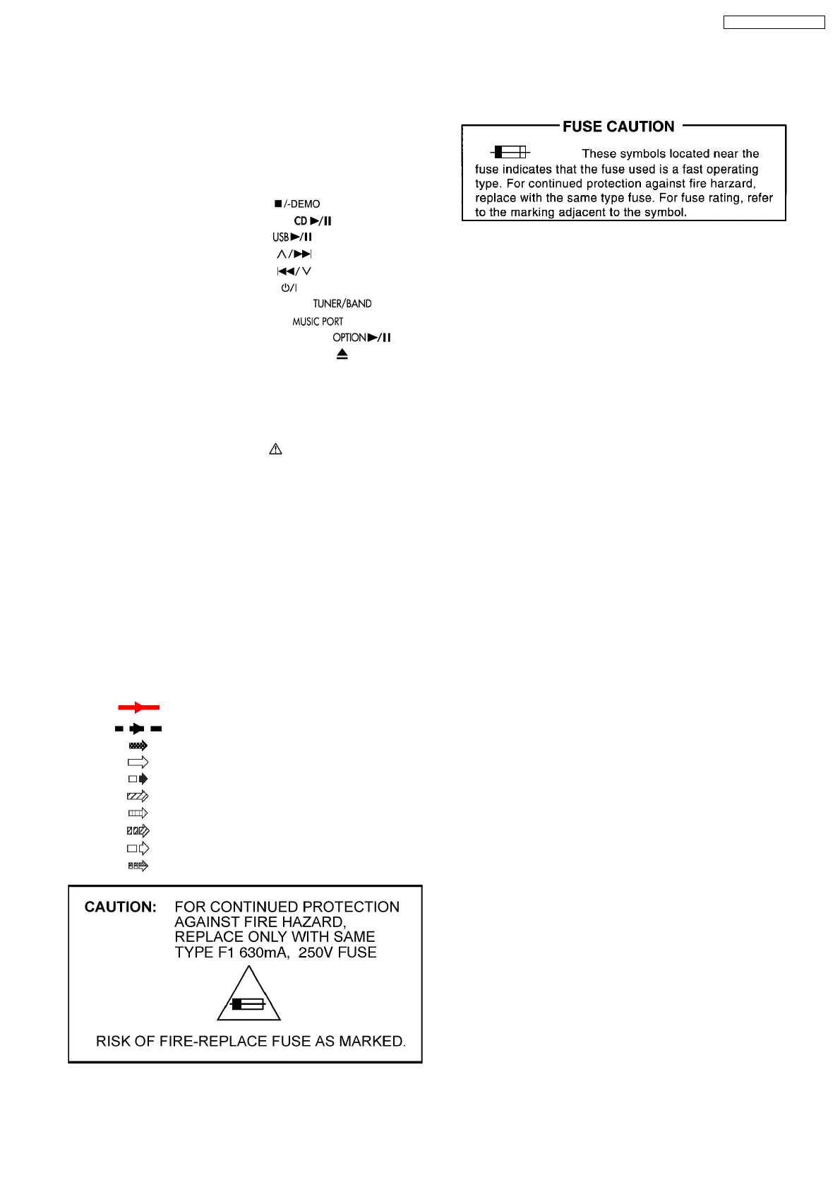
Notes:
S700: Mecha-up switch.
S701: Mecha-down switch.
S900: Stop switch. (
)
S901: CD Play switch. (
)
S902: USB switch. (
)
S903: FWD switch. (
)
S904: REW switch. (
)
S907: Power switch (
).
S909: Tuner/Band switch. (
)
S910: Music P switch. (
)
S911: Option / D-Port switch. (
)
S912: CD Open/Close switch. (
)
S7201: Rest switch.
VR900: Volume jog.
·
Importance safety notice :
Components identified by
mark have special
characteristics important for safety.
Furthe rmore, special parts which have purposes of fire-
retardant (resistors), high-quality sound (capacitors), low-
noise (resistors), etc. are used.
When replacing any of components, be sure to use only
manufacturer´s specified parts shown in the parts list.
·
Capacitor values are in microfarad(µF) unless specified
otherwise, F=Farad, pF=Pico-Farad
Resistance values are in ohm(Ω), unless specified
otherwise, 1K=1,000Ω, 1M=1,000KΩ
·
Voltage and Signal lines:
: +B Signal line
: -B Signal line
: CD-DA signal line
: CD signal line
: FM/AM signal line
: MAIN signal line
: D-PORT signal line
: AUX signal line
: FM signal line
: USB signal line
14 Notes Of Schematic Diagram
55
SA-NS55E / SA-NS55EG
 Loading...