© Panasonic Corporation 2010. All rights reserved.
Unauthorized copying and distribution is a violation of
law.
PSG1006031CE
A6
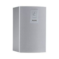
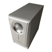
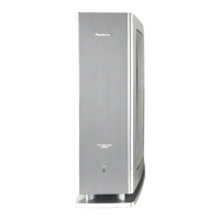
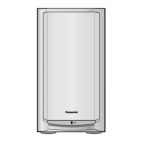
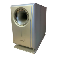
Wireless Subwoofer Unit
Model No. SB-WA500PP
Product Color: (K)...Black Type
TABLE OF CONTENTS
PAGE PAGE
1 Safety Precautions----------------------------------------------- 3
1.1. General Guidelines---------------------------------------- 3
1.2. Before Repair and Adjustment ------------------------- 4
1.3. Protection Circuitry ---------------------------------------- 4
1.4. Safety Part Information----------------------------------- 4
2 Warning-------------------------------------------------------------- 5
2.1. Prevention of Electro Static Discharge (ESD)
to Electrostatically Sensitive (ES) Devices---------- 5
2.2. Service caution based on Legal restrictions -------- 6
3 Service Navigation ----------------------------------------------- 7
3.1. Service Information --------------------------------------- 7
4 Specifications ----------------------------------------------------- 8
5 Location of Controls and Components ------------------- 9
5.1. Main Unit Key Button Operations---------------------- 9
6 Self diagnostic and special mode setting---------------10
6.1. Service Mode ----------------------------------------------10
7 Disassembly and Assembly Instructions ---------------11
7.1. Disassembly flow chart----------------------------------12
7.2. Main Parts Location Diagram--------------------------12
7.3. Disassembly of Side Panel Unit ----------------------13
7.4. Disassembly of Passive Radiator ------------------- 14
7.5. Disassembly of Woofer Speaker (SP61) ---------- 15
7.6. Disassembly of Amp Module Assembly ----------- 16
7.7. Disassembly of AC Inlet P.C.B. ---------------------- 17
7.8. Disassembly of SMPS Module P.C.B. ------------- 17
7.9. Disassembly of Digital Receiver (RX) Module
P.C.B. ------------------------------------------------------- 18
7.10. Disassembly of ID Switch P.C.B. and D-Amp
P.C.B. ------------------------------------------------------- 19
7.11. Replacement of Switch Regulator IC (IC5200)
---------------------------------------------------------------- 20
8 Service Position ------------------------------------------------- 23
8.1. Checking and Repairing of D-Amp P.C.B. --------- 23
9 Voltage Measurement & Waveform Chart--------------- 24
9.1. D-AMP P.C.B. --------------------------------------------- 24
9.2. Waveform Chart ------------------------------------------ 24
10 Illustration of IC’s, Transistors and Diodes ------------ 25
11 Block Diagram --------------------------------------------------- 27
11.1. RECEIVER BLOCK DIAGRAM----------------------- 27
12 Wiring Connection Diagram--------------------------------- 29